
A4 Mk3
|
| Front axle | Standard running gear (1BA) | China city running gear (1BB) | Sports running gear (1BE/1BD) | Steel spring running gear, allroad (1BP) |
| Camber | - 43′ ± 23′ → Remark | - 43′ ± 23′ | - 1°5′ ± 23′ | - 20′ ± 23′ |
| Maximum permissible difference between left and right | 30′ | 30′ | 30′ | 30′ |
| Toe setting for each wheel (specification when making adjustment) | + 10′ ± 5′ | + 10′ ± 5′ | + 10′ ± 5′ | + 10′ ± 5′ |
| Toe setting for each wheel (specification when checking adjustment) | + 10′ ± 7′ | + 10′ ± 7′ | + 10′ ± 7′ | + 10′ ± 7′ |
| Toe-out on turns at 20 degrees steering angle → Remark | 1° 49′ ± 30′ | 1° 49′ ± 30′ | 1° 49′ ± 30′ | 1° 49′ ± 30′ |
| Outer wheel steering angle at full lock | 33° 12' + 1° 30'- 2° | 33° 12' + 1° 30'- 2° | 33° 12' + 1° 30'- 2° | 33° 12' + 1° 30'- 2° |
| Inner wheel steering angle at full lock | 39° 36' + 1° 30'- 2° | 39° 36' + 1° 30'- 2° | 39° 36' + 1° 30'- 2° | 39° 36' + 1° 30'- 2° |
|
| Front axle | Running gear with electronic damping control (1BL) | Heavy-duty running gear (1BR) | Sports running gear, S line (1BV) |
| Camber | - 1°5′ ± 23′ | - 30′ ± 23′ | - 1°13′ ± 23′ |
| Maximum permissible difference between left and right | 30′ | 30′ | 30′ |
| Toe setting for each wheel (specification when making adjustment) | + 10′ ± 5′ | + 10′ ± 5′ | + 10′ ± 5′ |
| Toe setting for each wheel (specification when checking adjustment) | + 10′ ± 7′ | + 10′ ± 7′ | + 10′ ± 7′ |
| Toe-out on turns at 20 degrees steering angle → Remark | 1° 49′ ± 30′ | 1° 49′ ± 30′ | 1° 49′ ± 30′ |
| Outer wheel steering angle at full lock | 33° 12' + 1° 30'- 2° | 33° 12' + 1° 30'- 2° | 33° 12' + 1° 30'- 2° |
| Inner wheel steering angle at full lock | 39° 36' + 1° 30'- 2° | 39° 36' + 1° 30'- 2° | 39° 36' + 1° 30'- 2° |
| Rear axle | Standard running gear (1BA) | China city running gear (1BB) | Sports running gear (1BE)/(1BD) | Steel spring running gear, allroad (1BP) |
| Camber | - 1°20′ ± 25′ | - 1°20′ ± 25′ | - 1°20′ ± 25′ | - 1°20′ ± 25′ |
| Maximum permissible difference between left and right | 30′ | 30′ | 30′ | 30′ |
| Toe setting for each wheel (specification when making adjustment) | + 10′ ± 5′ | + 10′ ± 5′ | + 10′ ± 5′ | + 10′ ± 5′ |
| Toe setting for each wheel (specification when checking adjustment) | + 10′ ± 5′ | + 10′ ± 5′ | + 10′ ± 5′ | + 10′ ± 5′ |
| Maximum permissible deviation in direction of travel relative to longitudinal axis of vehicle | 10′ | 10′ | 10′ | 10′ |
| Rear axle | Running gear with electronic damping control (1BL) | Heavy-duty running gear (1BR) | Sports running gear, S line (1BV) |
| Camber | - 1°20′ ± 25′ | - 1°20′ ± 25′ | - 1°20′ ± 25′ |
| Maximum permissible difference between left and right | 30′ | 30′ | 30′ |
| Toe setting for each wheel (specification when making adjustment) | + 10′ ± 5′ | + 10′ ± 5′ | + 10′ ± 5′ |
| Toe setting for each wheel (specification when checking adjustment) | + 10′ ± 5′ | + 10′ ± 5′ | + 10′ ± 5′ |
| Maximum permissible deviation in direction of travel relative to longitudinal axis of vehicle | 10′ | 10′ | 10′ |
|
 Note
Note
|
|
| Camber settings at front wheels for right-hand drive vehicles with standard running gear (1BA) | ||||||
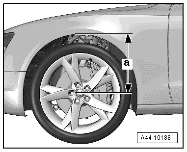
| Vehicle height | Camber | Max. perm. height diff. between right and left | ||||
| Trend | Absolute mean of left and right wheel | Mean delta in rel. to specified vhcl. height in mm | Checking/adjustment setting | Tolerance | Maximum permissible difference between left and right | |
| Too high | 401 | 10 | -33′ | ± 23′ | 30′ | ≤ 10 mm |
| 400 | 9 | -34′ | ||||
| 399 | 8 | -35′ | ||||
| 398 | 7 | -36′ | ||||
| 397 | 6 | -37′ | ||||
| 396 | 5 | -38′ | ||||
| 395 | 4 | -39′ | ||||
| 394 | 3 | -40′ | ||||
| 393 | 2 | -41′ | ||||
| 392 | 1 | -42′ | ||||
| Spec. | 391 | 0 | -43′ | |||
| Too low | 390 | -1 | -44′ | |||
| 389 | -2 | -45′ | ||||
| 388 | -3 | -46′ | ||||
| 387 | -4 | -47′ | ||||
| 386 | -5 | -48′ | ||||
| 385 | -6 | -49′ | ||||
| 384 | -7 | -50′ | ||||
| 383 | -8 | -51′ | ||||
| 382 | -9 | -52′ | ||||
| 381 | -10 | -53′ | ||||
|