
A4 Mk3
|
 Note
Note
|
|
Note
|
|
|
|
Note
|
|
|
|
Note
|
|
|
|
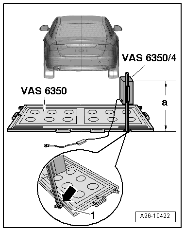
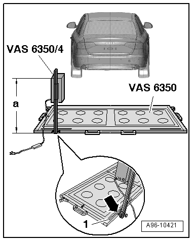
| Setting dimension (height) in mm | Saloon up to model year 2012 | Avant up to model year 2012 | allroad up to model year 2012 | Saloon from model year 2013 onwards | Avant from model year 2013 onwards | allroad from model year 2013 onwards |
| 700 | 700 | 770 | 765 | 783 | 823 |
|
| Setting dimension (right-side) in mm | Saloon up to model year 2012 | Avant up to model year 2012 | allroad up to model year 2012 | Saloon from model year 2013 onwards | Avant from model year 2013 onwards | allroad from model year 2013 onwards | |
| SWA 1.0 | 586 | ||||||
| SWA 1.5 | 745 | 745 | 830 | ||||
| SWA 2.0 | 592 | 641 | 643 | ||||
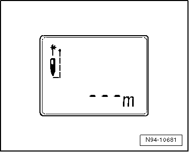
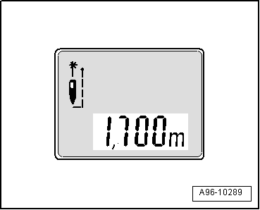
| Read off from measuring scale -1-. | |||||||
|
|
|
|
|
|
|
Note
|
|
|
|
| Setting dimension (height) in mm | Saloon up to model year 2012 | Avant up to model year 2012 | allroad up to model year 2012 | Saloon from model year 2013 onwards | Avant from model year 2013 onwards | allroad from model year 2013 onwards |
| 700 | 700 | 770 | 765 | 783 | 823 |
|
| Setting dimension (left-side) in mm | Saloon up to model year 2012 | Avant up to model year 2012 | allroad up to model year 2012 | Saloon from model year 2013 onwards | Avant from model year 2013 onwards | allroad from model year 2013 onwards | |
| SWA 1.0 | 586 | ||||||
| SWA 1.5 | 745 | 745 | 830 | ||||
| SWA 2.0 | 592 | 641 | 643 | ||||
| Read off from measuring scale -1-. | |||||||
|
|