audi Workshop Repair Guides

Audi Workshop Service and Repair Manuals

Pin assignment at entry and start authorisation switchE415 > < Removing and installing turn signal switchE2, cruise control system switchE45, intermittent wiper switchE22
Removing and installing entry and start authorisation switchE415
Removing and installing entry and start authorisation switch -E415-
  Note
t  Reader coil for immobilizer is attached to entry and start authorisation switch -E415- and cannot be renewed separately.
t  The entry and start authorisation switch -E415- must be renewed if reading coil is defective.
t  Adaption to immobilizer is not necessary if the entry and start authorisation switch is renewed.
t  The lock in the entry and start authorisation switch is not mechanically coded.
t  Therefore the keys must not be renewed after renewing entry and start authorisation switch (continue to use old keys).
Special tools and workshop equipment required
   
t  Ignition lock removal pliers -VAS 6339-
Removing
–  Remove dash panel trim (driver's side) → Rep. gr.68.
–  On USA vehicles, remove impact damper (right-side) → Rep. gr.70.
–  Remove cover for MMI screen → Rep. gr.70.
–  Remove trim cover for instrument cluster → Rep. gr.68.
  W00-10373
–  Remove bolt -2- for trim panel -1-.
  A70-10679
–  Insert ignition lock removal pliers -VAS 6339- through flaps of trim panel.
–  Position pointed ends of ignition lock removal pliers -VAS 6339- at the two holes -arrows A- on entry and start authorisation switch -E415--2-.
–  Press -VAS 6339- together -arrows B-; this will pry apart pointed ends of pliers and release retaining tabs on trim panel.
–  Keep -VAS 6339- pressed with one hand and pull off trim panel -1--arrow C- with the other hand.
  Note
Detach trim panel by hand and use ignition lock removal pliers -VAS 6339- for releasing only.
  A70-10833
–  Remove bolt -2-.
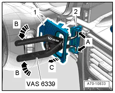
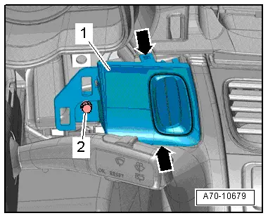
–  Take entry and start authorisation switch -E415--item 1- out of dash panel towards front in direction of driver's footwell.
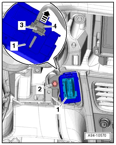
–  Unplug electrical connector -3- by sliding locking element -4- upwards -arrow- and pressing release catch inwards.
Installing
l  Tightening torque → Fig.
Installation is carried out in the reverse order; note the following:
–  Install trim cover for instrument cluster → Rep. gr.68.
–  Install cover for MMI screen → Rep. gr.70.
–  On USA vehicles, install impact damper (right-side) → Rep. gr.70.
–  Install dash panel trim (driver's side) → Rep. gr.68.
  A94-10570

Pin assignment at entry and start authorisation switchE415 > < Removing and installing turn signal switchE2, cruise control system switchE45, intermittent wiper switchE22