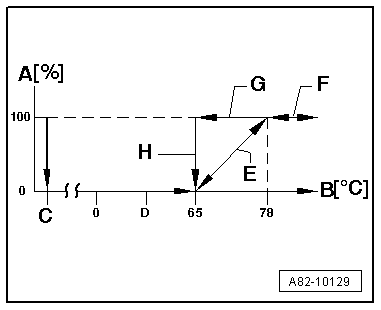
| A = This proportion of the coolant in % is conveyed in the large coolant circuit. |
| l
| If the heater coolant shut-off valve -N279- is not actuated, all the coolant flows in the large circuit (via the engine to the auxiliary heater). |
| l
| If the heater coolant shut-off valve -N279- is constantly actuated, all the coolant flows in the small circuit (directly from the heat exchanger in the air conditioner unit to the auxiliary heater). |
| l
| The heater coolant shut-off valve -N279- is actuated by the supplementary heater control unit -J364- in line with the coolant temperature and the request set. |
| B = Temperature of coolant in auxiliary heater in °C (centigrade). |
| C = Activation signal for auxiliary heater (the heater coolant shut-off valve -N279- is actuated and the coolant flows back from the heat exchanger in the air conditioner unit to the auxiliary heater). |
| D = The auxiliary heater is in auxiliary heating full load mode, the coolant temperature increases (or remains constant). All the coolant drawn in by the circulation pump -V55- comes from the front air conditioner heat exchanger. |
| E = The auxiliary heater is in auxiliary heating full or part load mode. Depends on the characteristic curve stored in the supplementary heater control unit -J364-. The coolant temperature increases (or remains constant) and the proportion of the coolant (drawn in by the circulation pump -V55-) which flows back via the engine to the auxiliary heater is regulated by the supplementary heater control unit -J364-. |
| F = All the coolant drawn in by the circulation pump -V55- flows back via the engine to the auxiliary heater, the coolant temperature continues to increase (less heat is emitted by the air conditioner heat exchangers than is generated by the auxiliary heater or, for example, with the engine running). |
| G = All the coolant drawn in by the circulation pump -V55- flows back via the engine to the auxiliary heater, the coolant temperature decreases (more heat is emitted by the front air conditioner heat exchangers or the engine than is generated by the auxiliary heater and the engine). |
| H = The coolant temperature drops below 65 °C. |

Note | t
| Depending on the ambient temperature and the quantity of heat emitted by the air conditioner heat exchangers, the actuation of the heater coolant shut-off valve -N279- may remain in the various operating statuses for a lengthy period. |
| t
| Actuation of the heater coolant shut-off valve -N279- is also maintained if the engine is started with the auxiliary heater in operation (however only up to a certain engine speed on the Audi Q5). |
| t
| Different versions of the heater coolant shut-off valve -N279- (for Audi A5 Coupé, Audi A4 and Audi Q5); pay attention to correct assignment → Electronic parts catalogue. |
| t
| At a coolant temperature of approx. 89 °C, the auxiliary heater switches from control mode to control interval. During the control interval, the heater coolant shut-off valve -N279- is not actuated and the coolant flows in the large coolant circuit (via the engine). |
| t
| The display in the measured value block for actuation of the heater coolant shut-off valve -N279- differs and depends on the vehicle model and version of the supplementary heater control unit -J364-. On this vehicle, a display of 100 % for example currently indicates that 100 % of the coolant is being conveyed in the small circuit and that the heater coolant shut-off valve -N279- is being actuated → Vehicle diagnostic, testing and information systemVAS 5051 A, "Guided fault-finding" function. |
| t
| Depending on the vehicle model, the engine fitted, the coolant temperature and the setting on the operating and display unit, Climatronic control unit -J255-, -N279- may also be actuated by the supplementary heater control unit -J364- with the auxiliary heater switched off. In this case, actuation is in response to a request from the operating and display unit, Climatronic control unit -J255- via the data bus → Air conditioning; Rep. Gr.87. |
| t
| Depending on the model and the engine, the vehicle may additionally be fitted with a non-return valve in the coolant circuit. A certain amount of coolant then flows back to the engine via this non-return valve in the small circuit if the heater coolant shut-off valve -N279- is being actuated → Chapter. |
|
|
|
