audi Workshop Repair Guides

Audi Workshop Service and Repair Manuals

Removing and installing gearbox > < Exploded view - torque converter
Electrical/electronic components and fitting locations
   
Diagnostic connector
t  Fitting location: the diagnosis connector for the vehicle diagnostic, testing and information system -VAS 5051B- is located in the driver's footwell.
  A00-10303
Mechatronic unit, automatic gearbox control unit -J217-, multifunction switch -F125-, gearbox input speed sender -G182- and gearbox output speed sender -G195-
t  
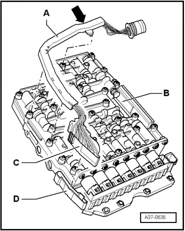
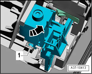
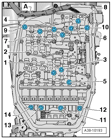
Fitting location: the mechatronic unit is bolted to the underside of the gearbox housing and covered by the gearbox oil pan.
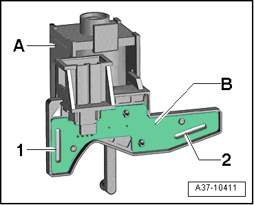
The mechatronic unit incorporates the hydraulic control system, the electronic control unit and the sensors and actuators as a complete synchronised unit. This includes:
t  Automatic gearbox control unit -J217-
t  Multi-function switch -F125-
t  Gearbox input speed sender -G182-
t  Gearbox output speed sender -G195-
The “mechatronic” unit can only be replaced as a complete unit.
  Note
All components mentioned are tested via Self-diagnosis.
→ Chapter „Removing and installing mechatronic unit“.
  A38-10193
Wiring harness in gearbox
t  Fitting location: the wiring harness -A- with connector -C- is attached to the mechatronic unit -B-.
→ Chapter „Removing and installing wiring harness in gearbox“.
  A37-0636
Selector lever position display -Y6-
t  Fitting location: The selector lever position display -Y6- is integrated in the instrument cluster.
  Note
If the selector lever position display is defective, renew the instrument cluster → Rep. Gr.90.
  A37-10920
Selector lever sensors control unit -J587- and tiptronic switch -F189-
t  Fitting location: the selector lever sensors control unit -J587- and the tiptronic switch -F189- are combined in a single component -2- which is clipped onto the shift unit -arrows-.
  Note
-Arrows A- can be disregarded.
→ Chapter „Removing and installing selector lever sensors control unit -J587- and tiptronic switch -F189-“.
  A37-10416
Selector lever lock solenoid -N110-
t  Fitting location: the selector lever lock solenoid -N110--item 1- is clipped onto the selector mechanism.
→ Chapter „Removing and installing selector lever lock solenoid -N110-“.
  A37-10413
Gear selector position P switch -F305-
t  Fitting location: Gear selector position P switch -F305- consists of two reed contacts (-1- and - 2-) and is installed on printed circuit board -B- in selector lever lock solenoid -N110--A-.
  Note
Gear selector position P switch -F305- can only be renewed together with selector lever lock solenoid -N110-.
→ Chapter „Removing and installing selector lever lock solenoid -N110-“.
  A37-10411
Kickdown switch -F8-
  Note
The engine control unit stores a specific value received from the accelerator position sender -G79- and the accelerator position sender 2 -G185-.
t  Fitting location: the accelerator position senders are integrated in the accelerator pedal module -arrow-.
  Note
Renew accelerator pedal module if accelerator position sender is defective → Rep. Gr.20.
  A24-0204
Selector lever position display -Y26-
t  Fitting location: the display unit for selector lever position -Y26--item 1- is clipped into the centre console.
→ Chapter „Removing and installing selector lever position display -Y26-“.
  A96-10070

Removing and installing gearbox > < Exploded view - torque converter