
A5
| Exploded view - dismantling and assembling gearbox |
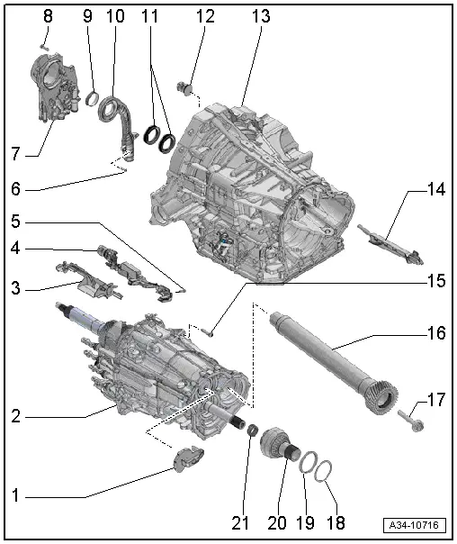
| 1 - | Oil duct |
| q | For input shaft |
| 2 - | Intermediate gearbox housing |
| q | With gear cluster |
| 3 - | Oil collector (front) |
| q | Clipped onto sensor module |
| 4 - | Sensor module |
| q | For senders and sensors -G612-/ -G632-/ -G676- |
| q | Different versions are available; for correct version refer to → Electronic parts catalogue |
| q | Removing and installing → Chapter |
| 5 - | Bolt |
| q | 8 Nm |
| q | Different versions are available; for correct version refer to → Electronic parts catalogue |
| 6 - | Bolt |
| q | 4.5 Nm |
| 7 - | Oil pump |
| q | Removing and installing → Chapter |
| 8 - | Bolt |
| q | 5x |
| q | 8 Nm |
| 9 - | O-ring |
| q | Renew |
| q | Different versions possible |
| 10 - | Suction-jet pump |
| q | Renew small O-ring (not shown in illustration) |
| 11 - | Oil seal |
| q | Twin-lip oil seal (two parts are pressed together) |
| q | For partition in gearbox housing |
| q | Renewing → Chapter |
| 12 - | Connector housing for sensor module |
| q | Removing and installing → Chapter „Removing and installing sensor module for senders and sensors -G612-/ -G632-/ -G676-“ |
| 13 - | Gearbox housing |
| 14 - | Oil duct |
| q | Leading to front axle drive |
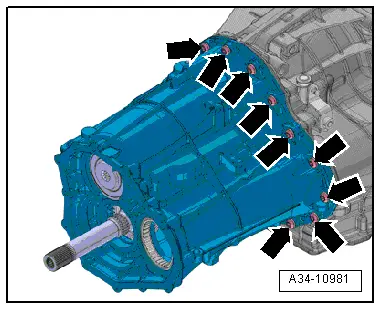
| 15 - | Bolt |
| q | Renew |
| q | Tightening torque and sequence → Fig. |
| 16 - | Side shaft |
| q | With spur gear |
| 17 - | Bolt |
| q | Secures side shaft to pinion shaft |
| q | Renew |
| q | 150 Nm +90° |
| 18 - | Shim |
| 19 - | Spacer sleeve |
| 20 - | Spur gear |
| 21 - | Needle bearing |
 Note
Note
|
|
| Stage | Bolts | Tightening torque/tightening angle |
| 1. | -arrows- | 8 Nm in diagonal sequence |
| 2. | -arrows- | Turn 120° further in diagonal sequence |