
A5
| Valve gear - exploded view |
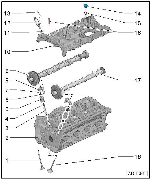
| 1 - | Exhaust valve |
| q | Do not machine, only grinding-in is permitted |
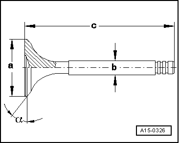
| q | Valve dimensions → Fig. |
| q | Checking valve guides → Chapter |
| 2 - | Cylinder head |
| 3 - | Valve guide |
| q | Checking → Chapter |
| 4 - | Valve stem oil seal |
| q | Renewing → Chapter „Renewing valve stem oil seals with cylinder head installed“ → Chapter „Renewing valve stem oil seals with cylinder head removed“ |
| 5 - | Valve spring |
| 6 - | Valve spring plate |
| 7 - | Valve cotters |
| 8 - | Hydraulic compensation element |
| q | Do not interchange |
| q | Lubricate contact surface |
| 9 - | Exhaust camshaft |
| q | Removing and installing → Chapter |
| q | Check radial clearance with Plastigage (roller rocker fingers removed) |
| q | Radial clearance: 0.024 ... 0.066 mm |
| q | Runout: max. 0.04 mm |
| 10 - | Cylinder head cover |
| q | With integrated camshaft bearings |
| q | Clean sealing surface; machining not permitted |
| q | Remove old sealant residues |
| 11 - | O-ring |
| q | Renew |
| q | Lubricate with engine oil |
| 12 - | Actuator for variable valve timing |
| 13 - | Bolt |
| q | 5 Nm |
| 14 - | O-ring |
| q | Renew |
| q | Lubricate with engine oil |
| 15 - | Sealing plug |
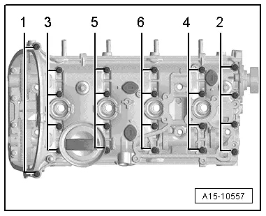
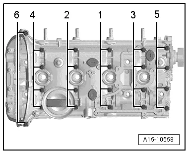
| 16 - | Bolt |
| q | Renew |
| q | Slackening → Fig. |
| q | Tightening sequence → Fig. |
| 17 - | Inlet camshaft |
| q | Removing and installing → Chapter |
| q | Check radial clearance with Plastigage (roller rocker fingers removed) |
| q | Radial clearance: 0.024 ... 0.066 mm |
| q | Runout: max. 0.04 mm |
| 18 - | Inlet valve |
| q | Do not machine, only grinding-in is permitted |
| q | Valve dimensions → Fig. |
| q | Checking valve guides → Chapter |
|
|
 Note
Note
|
|
| Dimension | Inlet valve | Exhaust valve | |
| Ø a | mm | 33.85 ± 0.10 | 28.0 ± 0.1 |
| Ø b | mm | 5.98 ± 0.01 | 5.96 ± 0.01 |
| c | mm | 104.0 ± 0.2 | 101.9 ± 0.2 |
| α | ∠° | 45 | 45 |