audi Workshop Repair Guides

Audi Workshop Service and Repair Manuals

Engine cooling > < Oil filter bracket, engine oil cooler and oil supply line
Removing and installing sump
Special tools and workshop equipment required
   
t  T-bar and socket, 10 mm -3185-
  W00-0331
t  Allen key, long reach -T10058-
  W00-1006
t  Used oil collection and extraction unit -V.A.G 1782-
  W00-10211
t  Support bracket -10 - 222 A-
Removing
  W00-0225
–  Remove engine cover panel -arrows-.
  A10-11050
–  Set up support bracket -10 - 222 A- with adapters -10 - 222 A /3- on suspension turrets (left and right) as illustrated.
–  Attach spindles -10 - 222 A /11- to engine lifting eyes.
–  Partly take up weight of engine with spindles.
–  Remove front wheels.
–  Remove noise insulation → Rep. gr.66.
–  Remove subframe cross brace → Rep. gr.40.
–  Remove subframe → Rep. gr.40.
–  Place used oil collection and extraction unit -V.A.G 1782- below engine and drain off engine oil.
  Note
Please observe requirements for disposal.
–  Detach connector from oil level and oil temperature sender -G266-.
–  Remove bolts securing sump to gearbox.
  A10-10991
–  Remove bolts -7-, -8- and -9- from side facing engine.
–  Unbolt sump.
–  If necessary, loosen sump by striking it lightly with a rubber hammer.
–  Remove sealant remaining on crankcase with flat scraper.
  WARNING
Wear safety goggles.
  A34-10493
–  Remove sealant residue on sump with a rotating brush, e.g. an electric drill with a plastic brush attachment.
–  Clean surfaces; they must be free of oil and grease.
Installing
Install in reverse order. Note the following:
Tightening torques → Chapter „Sump, oil pump, balance shaft assembly - exploded view“
  N17-0012
Securing engine to manual gearbox
  A34-10493
ItemBoltNm
1 3)M10x50 1)65
2 4)M12x100 2)30 + 90°
3 5), 6M12x75 2)30 + 90°
4…5 5)M12x120 2)30 + 90°
7…9M10x75 2)15 + 90°
10M12x50 2)30 + 90°
ADowel sleeves for centralising
l  1) Steel bolt - is not renewed
l  2) Renew bolts.
l  3) Also secures starter
l  4) Also secures starter, with additional spacer sleeve between starter and gearbox
l  5) Also secures cable retainer

  Note
t  Note the use-by date of the sealant.
t  The sump must be installed within 5 minutes after applying the silicone sealant.
   
–  Cut off nozzle of tube at front marking (Ø of nozzle approx. 3 mm).
–  Apply silicone sealant onto clean sealing surface of sump as illustrated. Sealant bead must:
t  be 2...3 mm thick.
t  Pass round bolt holes on inside as shown in illustration -arrows-.
  Note
The bead of sealant must not be thicker than specified, otherwise excess sealant can enter the sump and block the strainer in the oil intake pipe.
  N17-0019
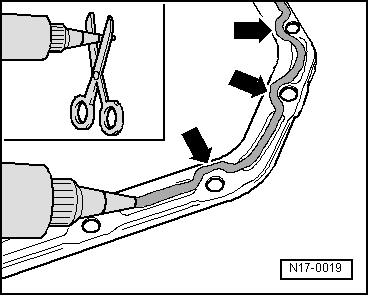
–  Apply bead of silicone sealant onto clean sealing surface of sump, as illustrated. (The illustration shows the position of the sealant bead on the crankcase.)
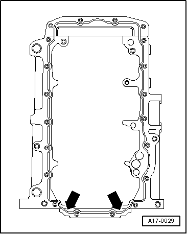
–  Immediately fit sump and lightly tighten bolts securing sump to gearbox and all bolts securing sump. The sump must make flush contact with spacer plate/gearbox flange.
  Note
When installing sump with engine removed from vehicle, ensure that sump is positioned flush with crankcase at flywheel end.
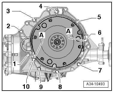
–  Tighten sump bolts in diagonal sequence.
–  Tighten sump/gearbox bolts.
  Note
After fitting sump assembly, the sealant must dry for approx. 30 minutes. Then (and only then) fill the engine with engine oil.
–  Fill with engine oil and check oil level (Audi A4) → Booklet812.
–  Fill with engine oil and check oil level (Audi A5) → Booklet811.
–  Install noise insulation → Rep. gr.66.
–  Install subframe cross brace → Rep. gr.40.
–  Install steering box → Rep. gr.48.
–  Install subframe → Rep. gr.40.
Further assembly is basically carried out in reverse order of dismantling.
  A17-0029

Engine cooling > < Oil filter bracket, engine oil cooler and oil supply line