
A5
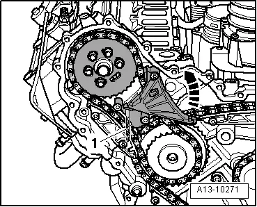
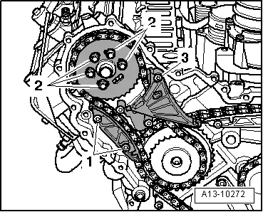
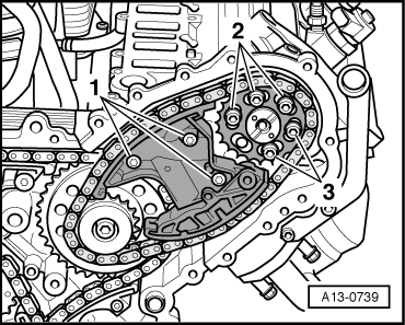
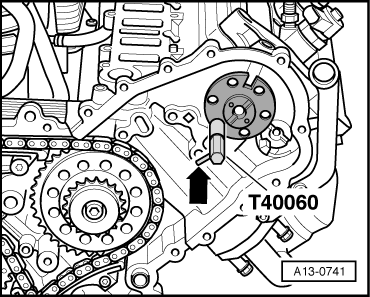
| Removing timing chains from camshafts |
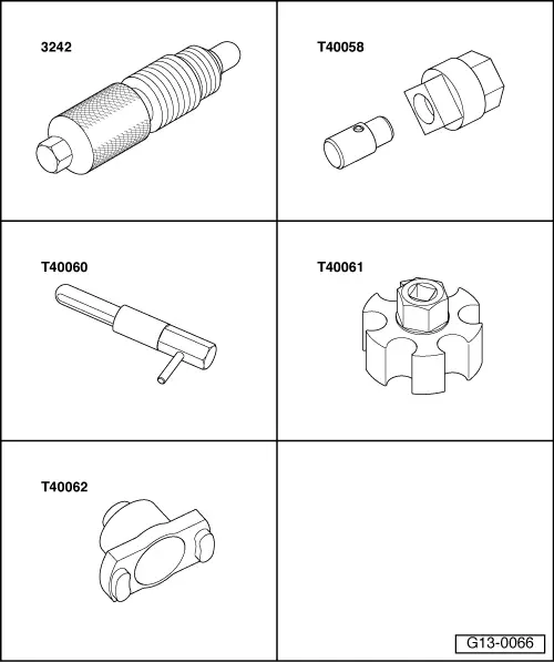
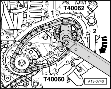
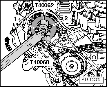
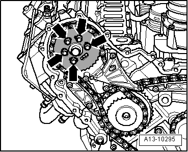
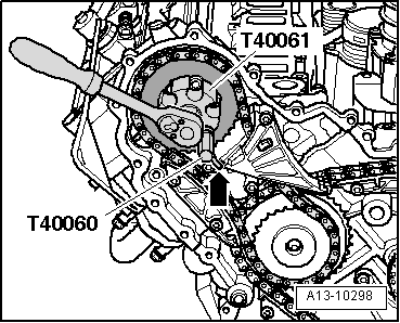
| Special tools and workshop equipment required |
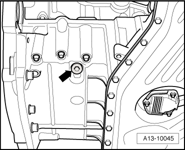
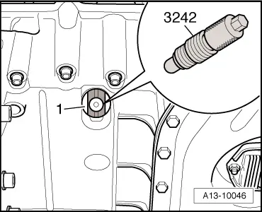
| t | Locking pin -3242- |
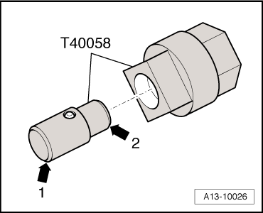
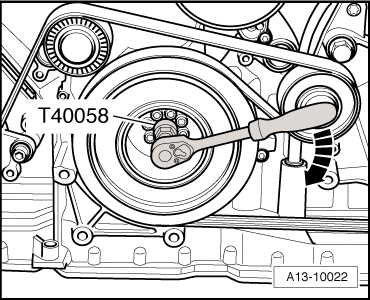
| t | Adapter -T40058- |
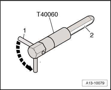
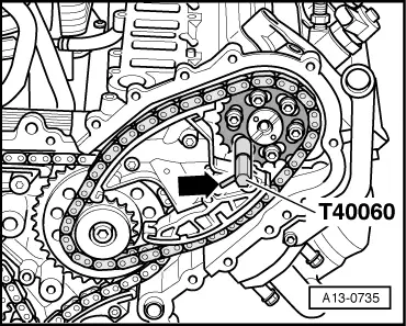
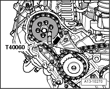
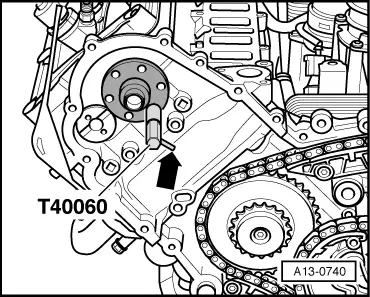
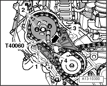
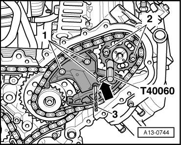
| t | 2x Adjustment pin -T40060- |
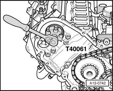
| t | Adapter -T40061- |
| t | Adapter -T40062- |
| t | Drill bit 3.3 mm Ø (2x) |
 Note
Note
|
|
|
Note |
|
 Caution
|
|
|
|
Note |
|
|
|
|
|
|
|
|
|
|

|
|
|
Note
|
|
|
|
|
|
Note
|
|
|
|
|
|
|
|
|
|
|
|
|
|
|
|
|
|
|
|
|
|
|
|