audi Workshop Repair Guides

Audi Workshop Service and Repair Manuals

Removing and installing exhaust gas temperature sender?3G495 > < Exhaust gas temperature senders - exploded view
Removing and installing exhaust gas temperature sender 1G235
Removing and installing exhaust gas temperature sender 1 -G235-
Special tools and workshop equipment required
   
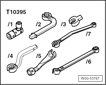
t  Tool set, 17 mm -T10395-
Removing
  Note
t  Fit all cable ties in the original positions when installing.
t  When removing, the electrical wiring must not be cut, otherwise a fault diagnosis would no longer be possible.
–  Remove plenum chamber partition panel → Rep. gr.50.
  W00-10767
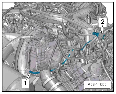
–  Unplug electrical connector -1-.
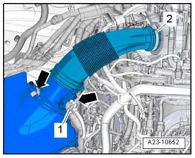
–  Remove air hose and air mass meter -G70-. To do so, release hose clip -2- and clamps -arrows-.
  A23-10652
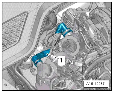
–  Press release tabs and disconnect crankcase breather hose -arrow-.
  A15-10987
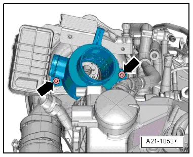
–  Remove bolts -arrows- and detach connection for turbocharger.
  A21-10537
–  Detach electrical connector -2- from bracket and unplug.
–  Unscrew exhaust gas temperature sender 1 -G235--item 1- using a tool from tool set, 17 mm -T10395-.
Installing
Installation is carried out in the reverse order; note the following:
Tightening torques:
l  → Chapter „Exhaust gas temperature senders - exploded view“.
l  → Chapter „Turbocharger - exploded view“.
l  → Chapter „Charge air cooler - exploded view“.
  Note
t  Fit new O-rings.
t  Take care to protect exhaust gas temperature sender from knocks and impact; if dropped, the exhaust gas temperature sender can no longer be used.
t  Coat thread with high-temperature paste; for high-temperature paste refer to → Electronic parts catalogue
–  Install plenum chamber partition panel → Rep. gr.50.
  A26-11006

Removing and installing exhaust gas temperature sender?3G495 > < Exhaust gas temperature senders - exploded view