
A5
| Checking fuel pressure and residual pressure (up to high-pressure pump) |
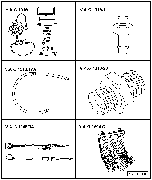
| Special tools and workshop equipment required |
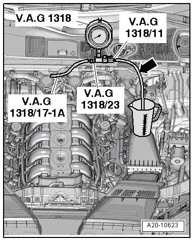
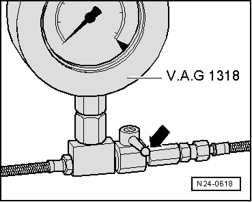
| t | K-Jetronic pressure tester -V.A.G 1318- |
| t | Adapter -V.A.G 1318/11- |
| t | Adapter set -V.A.G 1318/17A- |
| t | Connector -V.A.G 1318/23- |
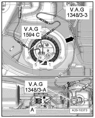
| t | Remote control -V.A.G 1348/3A- for V.A.G 1348 with adapter cable -V.A.G 1348/3-3- |
| t | Auxiliary measuring set -V.A.G 1594C- |
| t | Fuel-resistant measuring container |
|
|
|
 Note
Note
|
|
|
|
|
|
|
|
|
|
|
|
 WARNING
|
|
Note |
|
|
|