audi Workshop Repair Guides

Audi Workshop Service and Repair Manuals

Ignition system, glow plug system > < Wiring and component check with test boxV.A.G 1598/42
Renewing engine control unitJ623
Renewing engine control unit -J623-
Special tools and workshop equipment required
t  Hot air blower -VAS 1978/14A--item 1- with nozzle attachment -2- from wiring harness repair set -VAS 1978 B-
   
t  
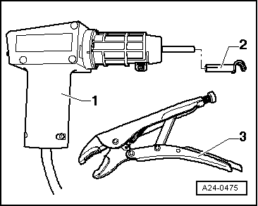
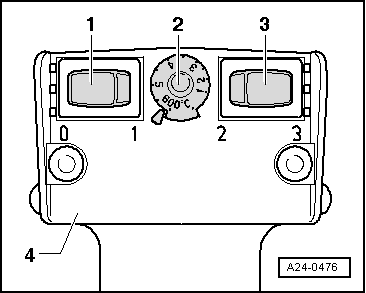
Small, commercially available mole grips -3-
Removing
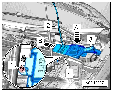
–  Before removing the engine control unit -J623-, the adaption values of the injectors and the ash deposit mass must be read out. Use → Vehicle diagnostic tester.
  Note
If the adaption values of the injectors cannot be read out of the old (defective) engine control unit, the adaption values must be entered into the new engine control unit manually and the adaption procedure must be performed accordingly.
–  Switch off ignition and remove ignition key after storing electronic file containing adaption values.
  Note
t  
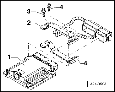
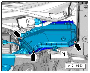
Not every engine control unit is bolted to a protective housing. Whether a protective housing is fitted depends on the engine/gearbox combination.
  A24-0475
t  The engine control unit -1- is bolted to the protective housing -5-. To make it more difficult to unscrew the shear bolts -4- for locking plate -2-, their threads have been coated with locking fluid.
t  The protective housing has to be removed before the connectors can be unplugged from the engine control unit (e.g. to connect the test box or renew the engine control unit).
  A24-0593
–  Slightly pull off rubber seal in front of nut -1- on plenum chamber cover.
–  Remove nut -1-.
–  Unhook wiring harness -2- from retainers -A-.
–  Pull filler neck -3- with filler pipe out of washer fluid reservoir and through opening in body.
  A92-10087
–  Unscrew bolts -arrows- and take off cover for electronics box.
  A10-10853
–  Release retainers -arrows A- and pull out engine control unit -J623--arrow B-.
  A10-10854
To help prevent unauthorised access to the connectors on the engine control unit, the engine control unit -1- is bolted on by means of locking plates -2 and 5- and shear bolts -3 and 4-.
The threads of the two shear bolts -4- which are not screwed into the engine control unit are secured with locking fluid. To unscrew these two bolts, the threads must therefore be heated with the hot air blower.
  A24-0593
The threads of the two shear bolts -3- which are screwed into the engine control unit are not secured with locking fluid. Do not apply heat to the threads in the control unit housing; this is not necessary and would cause overheating of the control unit.
  A24-0593
–  Select settings on hot air blower as shown in illustration, i.e. set temperature potentiometer -2- to maximum heat output and two-stage air flow switch -3- to position 3.
  WARNING
Heating the thread of the locking plate also heats up the shear bolts and parts of the metal housing. Take care to avoid burns. It is also important to ensure that only the thread is heated and none of the surrounding components if at all possible. These should be covered if necessary.
  A24-0476
Switch on the hot air blower and heat the bolt for approximately 20 ... 30 seconds.
–  Unscrew shear bolts using mole grips (see arrow in illustration).
  A24-0594
–  The two shear bolts screwed into the engine control unit do not need to be heated. They can be removed without heating.
–  Detach protective housing from control unit connectors.
–  Release connectors on engine control unit and unplug connectors.
–  Take out old engine control unit -J623- and install new engine control unit -J623-.
Installing
Installation is performed in the reverse sequence.
–  After installation, the protective housing must be re-fitted on the engine control unit -J623-.
–  Clean threaded holes for shear bolts to remove any residue from locking fluid. This can be done using a thread tap.
–  Always use new shear bolts.
l  Tightening torque for bolts securing cover of electronics box: 3.5 Nm.
The procedure required after connecting the new engine control unit is described in the Guided Fault Finding or Guided Functions. Use → Vehicle diagnostic tester.
–  The injector delivery calibration and the injector voltage calibration must additionally be re-adapted in the engine control unit -J623- after the control unit has been renewed (these functions influence engine power and exhaust emissions).
–  On vehicles with particulate filter the current mileage (km) reading must be stored in the engine control unit via an adaption procedure.
  A24-0595

Ignition system, glow plug system > < Wiring and component check with test boxV.A.G 1598/42