| t
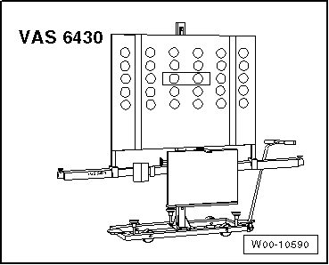
| ACC setting device -VAS 6430- |
| t
| Wheel alignment computer |

Note | t
| Check that the lane departure warning control unit -J759- is seated correctly in the bracket. |
| t
| Check that the camera vision is unobstructed (visual inspection). |
| t
| Before commencing calibration, interrogate event memory and rectify any faults. |
| t
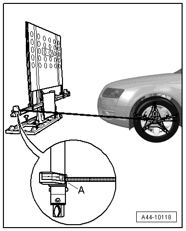
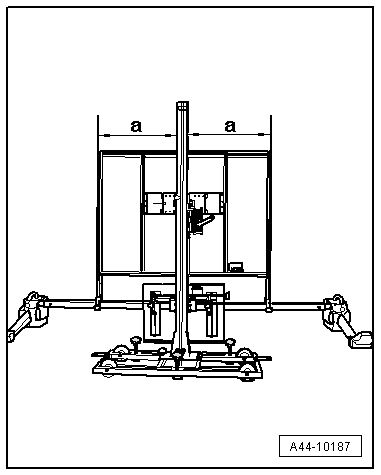
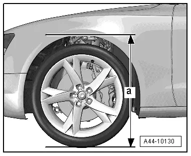
| Before driving the vehicle onto the alignment platform, make sure there is sufficient space between the hub centres of the front wheels and the setting device -VAS 6430-. The distance between -VAS 6430- and the hub centres of the front wheels must be 150 cm ± 2.5 cm. |
| t
| If the available space is not adequate, drive the vehicle backwards onto the alignment platform as required. |
| t
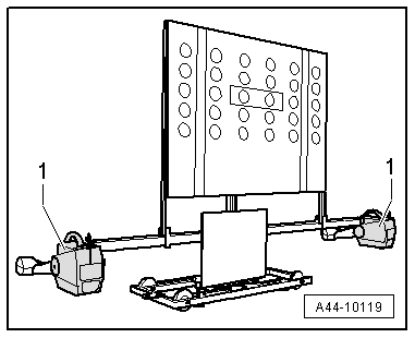
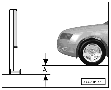
| Check the position of the calibration screen on the cross bar and align the calibration screen centrally if necessary. |
| –
| Observe test requirements for wheel alignment check → Chapter. |
| –
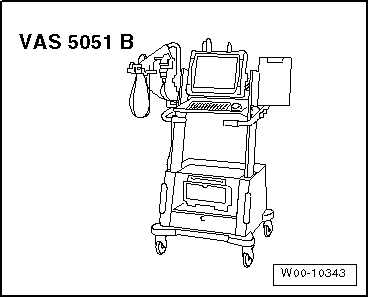
| Connect vehicle diagnosis, testing and information system -VAS 5051 B- to vehicle. (Run diagnosis cable through open window.) |
Note | During the calibration, make sure that all doors are closed on the vehicle and that the exterior lights are switched off. |
| –
| Set front wheels to straight-ahead position. |
| –
| Select calibration procedure for lane departure warning system in wheel alignment computer. |
| –
| Attach quick-release clamps to all four wheels. |
| –
| Attach rear wheel alignment sensors. |
| –
| Carry out wheel rim runout compensation for rear wheels. |
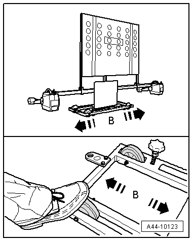
Note | Do not take hold of the cross bar when moving the -VAS 6430-. |
|
|
|