
3 Series E36 M3 (S50) COUPE
Input signals
12
ABS speed sensors
(ABS control unit)
14
ABS control braking
(SMG control unit)
15
Engine speed (DME control unit)
15
Engine temperature (DME control unit)
15
Engine oil temperature (DME control unit)
15
Intake air temperature (DME control unit)
15
Throttle valve potentiometer
(DME control unit)
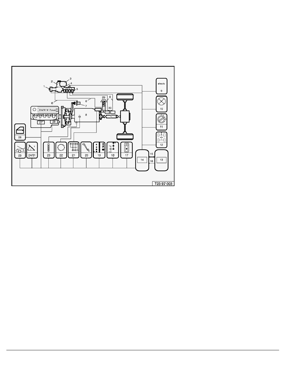
Fig. 2 SMG sensor system
Components
2
Hydraulic control unit
3
Pressure accumulator
5
Proportional control valves
6
Hydraulic lines
7
Clutch slave cylinder
8
Six-speed transmission
13
DME control unit
14
SMG control unit
16
CAN-bus
28
Starter motor
29
Actuator
30
Actuator
SMG hydraulic unit
The SMG hydraulic unit (item 12, Fig. 1 and Fig. 3) generates an oil pressure of about
60 to 80 bar through the electrically operated hydraulic pump (4) and provides the quantity of oil required to
execute the clutch and gear shift operations. Other components of the SMG hydraulic unit are
-
The pressure accumulator (8), for storing volume/energy;
-
The oil pressure sensor (12), which feeds the current oil pressure to the SMG control unit to switch the hydraulic
pump on/off;
-
The pressure check valve (13), for reliable pressure limitation;
-
The non-return valve to prevent oil from flowing back when the pump is switched off;
-
The supply tank (9) and the expansion tank (11) for supplying oil for clutch operation and for the pump oil
circulation;
SBT Layout and purpose
BMW AG - TIS
10.02.2013 16:48
Issue status (12/2007) Valid only until next DVD is issued
Copyright
Page - 3 -