
3 Series E36 M3 (S50) COUPE
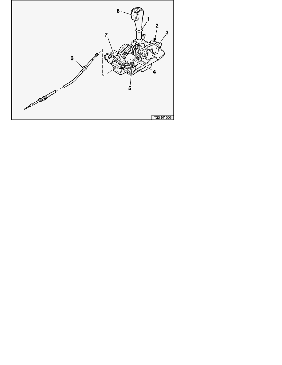
1
Selector lever
2
"S" detection microswitch
3
Manual gearshift (+/-) microswitch
4
Shift-lock magnet
5
Shift console
6
Actuator cable
7
Gear indicator microswitch with potentiometer
8
Reverse gear release button
The automatic shift gate has the following selector lever positions
R
= reverse gear
0
= neutral
E
= automatic program.
The respective position is recorded from a potentiometer linked to the selector lever.
In addition, regardless of the potentiometer, the selector lever position in the automatic shift gate is recorded by the
switch combination of two microswitches, transmitted to the SMG control unit and used for the selector lever position
indicator.
When the automatic program "E" is selected, all gears are selected automatically.
Fig. 6 Selector lever positions
SBT Layout and purpose
BMW AG - TIS
10.02.2013 16:48
Issue status (12/2007) Valid only until next DVD is issued
Copyright
Page - 6 -