
3 Series E36 M3 (S50) SAL
Layout and purpose
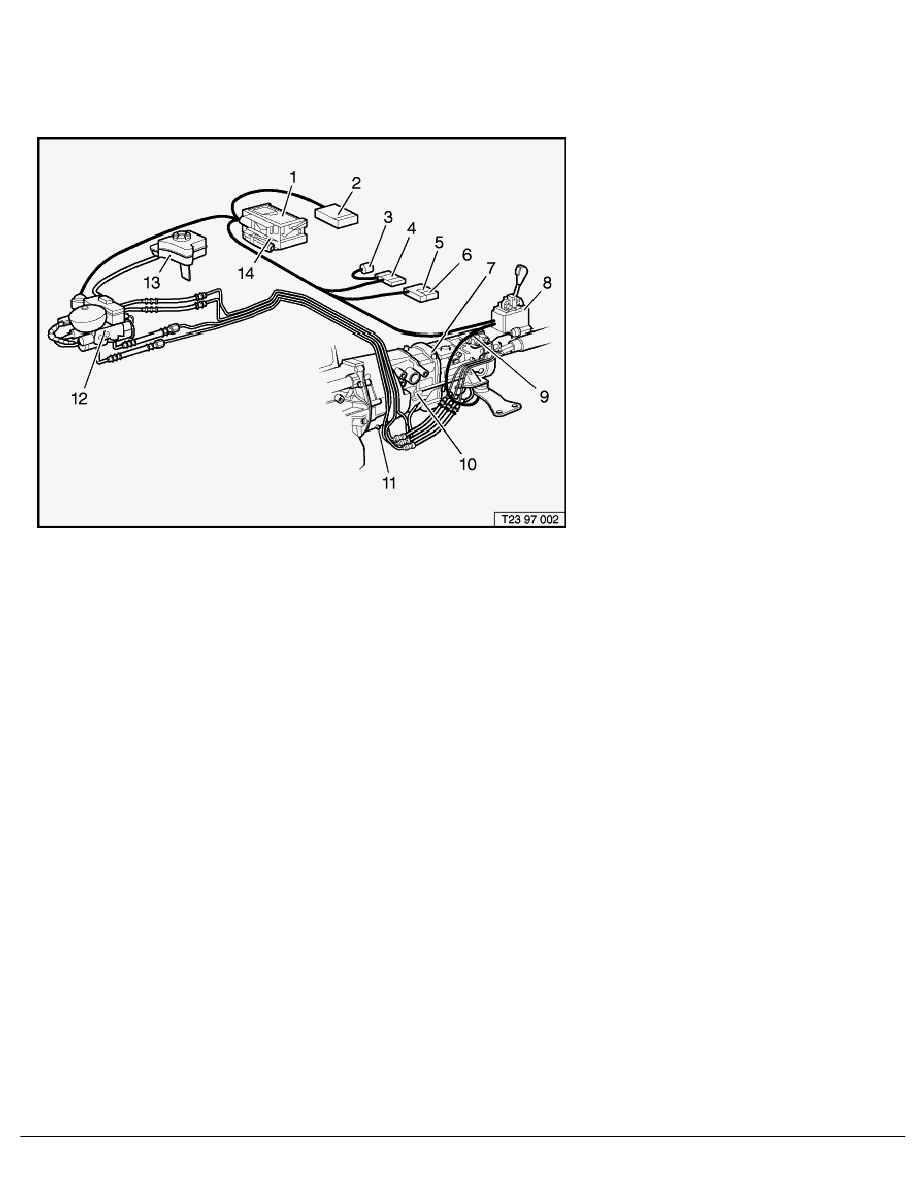
Complete SMG system
Figure 1 shows the complete SMG system.
Fig. 1 SMG components (without sensors)
1
SMG control unit
2
ABS control unit*
3
Gear and program indicator
(in revolution counter)
4
Control unit for gear and
program indicator
5
Program selector switch
(in centre console)
6
Selector lever position indicator
(in centre console)
7
Six-speed SMG transmission with actuator unit
8
SMG shift console
9
Cable
10
Clutch slave cylinder
11
Clutch (not illustrated)
12
Hydraulic control unit
13
Expansion tank
14
DME control unit*
* Peripheral parts, not SMG components
SMG control unit
The SMG control unit (1), which contains a printed circuit board with a microprocessor, is connected by wires
to the other components and sensors and to the DME and ABS control units.
Depending on the signals it receives from the sensors, it computes actuation signals for the hydraulic valves
to execute clutch operation and gear shifts. Moreover, it supplies information to the DME control unit (e.g.
engine speed adaptation), to the control unit for the gear and program indicator and to the selector lever
position indicator.
The SMG control unit has a non-volatile fault memory and is capable of diagnosis.
Figure 2 shows the input and output information/signals.
Fig. 2 SMG sensor system
SBT Layout and purpose
BMW AG - TIS
10.02.2013 16:24
Issue status (12/2007) Valid only until next DVD is issued
Copyright
Page - 1 -