
Century L4-2.2L VIN 4 (1994)
Knock Sensor Wiring Circuit
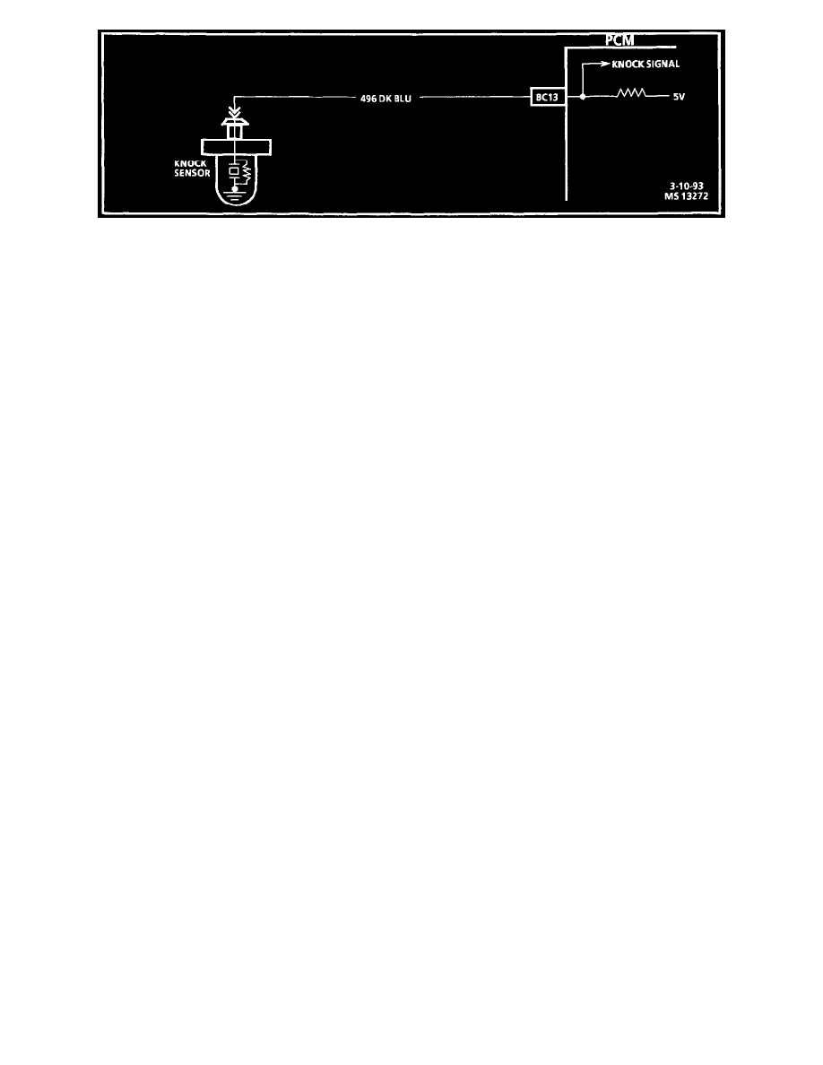
Circuit Description:
The knock sensor is used to detect engine detonation and the Powertrain Control Module (PCM) will retard the electronic spark timing based on the
signal being received. The knock sensor produces an AC signal. The amplitude and frequency are dependent upon the knock level.
The EPROM used with this engine contains the functions which were part of the remotely mounted Knock Sensor (KS) modules used on other GM
vehicles. The KS portion of the EPROM then sends a signal to other parts of the PCM which adjusts the spark timing to retard the spark and reduce the
detonation.
Chart Test Description: Number(s) below refer to circled number(s) on the diagnostic chart.
1.
If the engine has an internal problem which is creating a knock, the knock sensor may be responding to the mechanical noise.
2.
The Tech 1 scan tool displays knock sensor activity in counts approximately 50 at idle. The counts should increase when engine speed increases or
decreases when engine speed decreases. This step checks knock sensor activity.
3.
This step checks that the internal resistance of the knock sensor is within an acceptable range.
4.
Check the knock sensor connections for loose terminals or corrosion. A faulty connection may cause erratic operation. If the connections are OK,
check the components for erratic operation.
Diagnostic Aids: While observing knock signal on the Tech 1 scan tool, there should be an indication that knock is present when detonation can be
heard. Detonation is most likely to occur under high engine load conditions.