
Century V6-3.1L VIN J (2005)
Body Control Module: Description and Operation
Body Control System
BODY CONTROL SYSTEM DESCRIPTION AND OPERATION
BCM FUNCTIONS
The body control module (BCM) performs multiple body control functions. The BCM can control devices directly connected to its outputs based on
input information. The BCM evaluates this information and controls certain body control systems by commanding outputs on or off. The BCM control
inputs can be:
-
Sensors and switches that are directly connected to the BCM
-
Class 2 serial data received from other vehicle systems connected to the class 2 serial data link.
The BCM is also capable of controlling other vehicle systems that are not directly wired to the BCM. The BCM does this by sending specific
messages on the class 2 serial data link. The system capable of performing the required function will respond to the BCM message.
The BCM controls these functions:
-
Audible warnings-Refer to Audible Warnings Description and Operation (Audible Warnings) in Instrument Panel, Gages and Console.
-
Automatic door locks-Refer to Power Door Locks Description and Operation in Doors.
-
Automatic headlamp control-Refer to Exterior Lighting Systems Description and Operation in Lighting Systems.
-
Interior lighting-Refer to Interior Lighting Systems Description and Operation in Lighting Systems.
-
Keyless entry (AUO option)-Refer to Keyless Entry System Description and Operation in Keyless Entry.
-
Passlock theft deterrent-Refer to Vehicle Theft Deterrent (VTD) Description and Operation in Theft Deterrent.
-
Retained accessory power (RAP)-Refer to Retained Accessory Power (RAP) Description and Operation.
SIMPLE POWER MODE EXAMPLE
The power mode signal may be as simple as a B+ input wired to a particular ignition switch contact. If this is also the B+ supply to the module/device,
the module/device will only operate with the ignition contact closed to B+. An example of this is the starter relay when it is wired directly to the
CRANK/START contact of the ignition switch. When the CRANK/START contacts are closed, the starter relay is energized and provides a current
source to the starter and starter solenoid. When the ignition switch leaves the CRANK/START position, the switch contacts open and the starter relay
is de-energized. This removes the current source from the starter, solenoid, and the starter operation stops.
SERIAL DATA POWER MODE
On vehicles that have several control modules connected by serial data circuits, one module is the power mode master (PMM). On this vehicle, the
PMM is the body control module (BCM). The BCM receives 4 signals/circuits from the ignition switch. These are the Ignition 0, Ignition 1, Crank
and Accessory 1 ignition switch signals/circuits.
To determine the correct power mode the BCM uses:
-
The state of these signals/circuits, either switch closed (B+ = 1) or switch open (open = 0)
-
The sequence of switch closures received by the BCM
-
The status of the engine run flag.
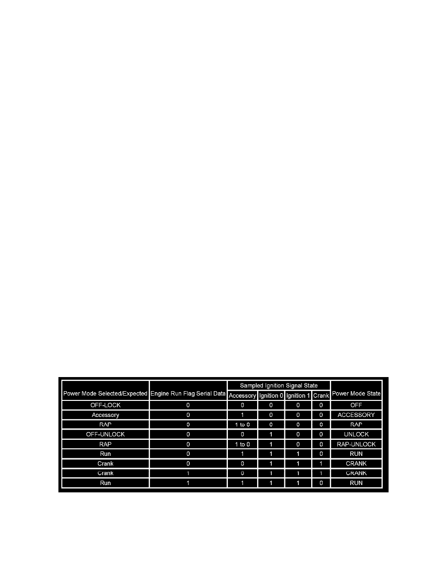
IMPORTANT: Any ignition switch state not covered in this table indicates a DTC setting situation.
The chart indicates the modes detected and transmitted by the BCM:
FAIL-SAFE OPERATION
Since the operation of the vehicle systems depends on the power mode, there is a fail-safe plan in place should the body control module (BCM) fail to
send a power mode message. The fail-safe plan covers modules with discrete ignition signal inputs as well as those modules using exclusively serial
data control of power mode.