
Century V6-3100 3.1L VIN M SFI (1998)
Knock Sensor: Testing and Inspection
Following is a short description of how the Knock Sensor (KS) can be diagnosed by using a scan tool. The scan tool can also be used to compare the
values for a normal running engine with the engine you are diagnosing.
DESCRIPTION
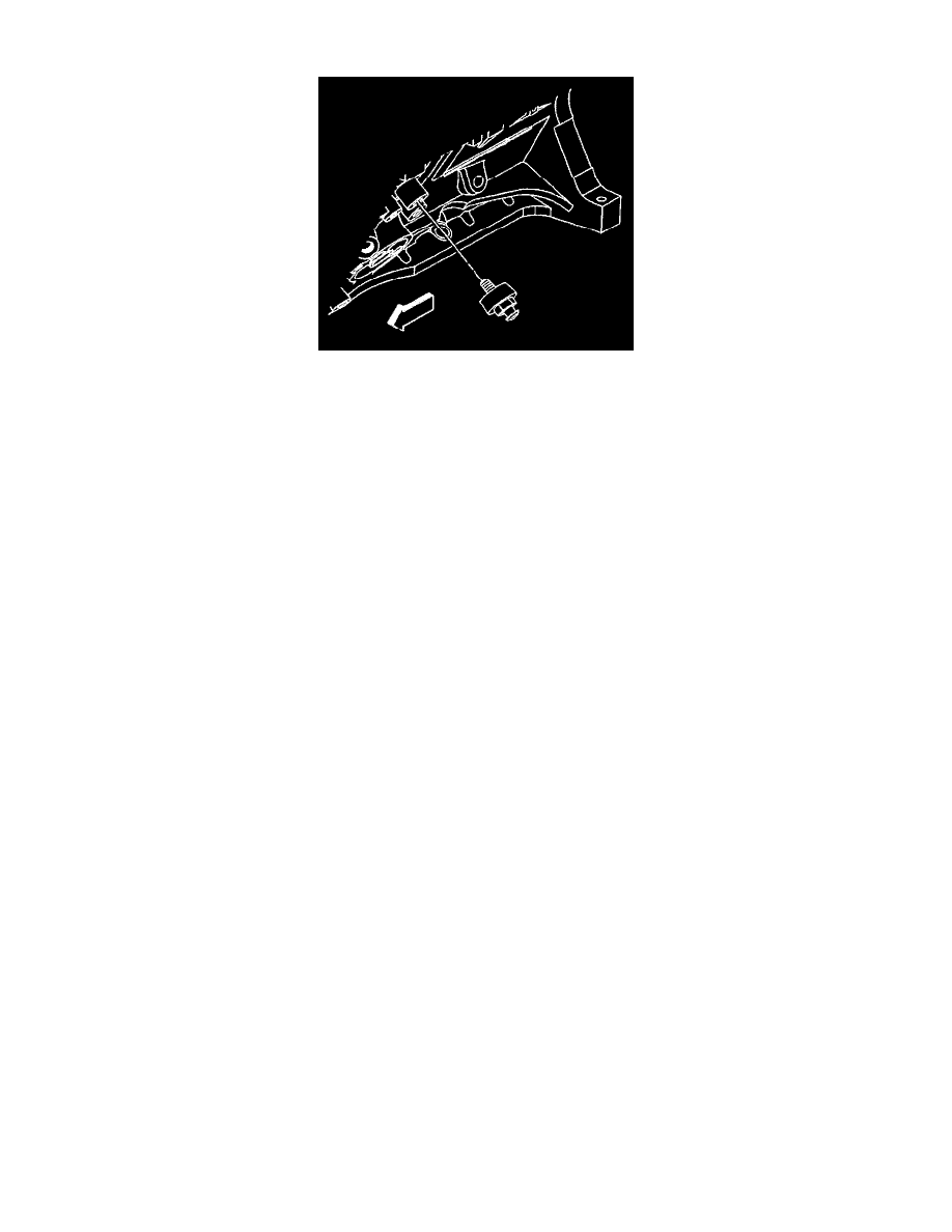
The knock sensors detect abnormal vibration (spark knocking) in the engine. The sensor is mounted in the engine block near the cylinders.
OPERATION
The knock sensors produce an AC voltage signal under all engine operating conditions. The PCM adjusts the Ignition Control (IC) spark timing based
on the amplitude and frequency of the KS signal being received.
DIAGNOSIS
The PCM contains integrated Knock Sensor (KS) diagnostic circuitry. The PCM uses the circuitry to diagnose the KS sensor and related wiring. The
PCM calculates an average voltage of each knock sensor's signal and takes instantaneous signal voltage readings. The PCM uses the instantaneous
signal voltage readings to determine the state of the knock sensor circuitry. If the knock sensor system is operating normally, the PCM should monitor
instantaneous KS signal voltage readings varying outside a voltage range above and below the calculated average voltage. If the PCM malfunctions in
a manner which will not allow proper diagnosis of the KS circuit DTC 0325 will set. DTC P0327 is designed to diagnose the knock sensor, and related
wiring, so problems encountered with the KS system should set a DTC. Refer to System Diagnosis / Diagnostic Tables / Diagnostic Trouble Code
Tables. See: Computers and Control Systems/Testing and Inspection
Refer to Knock Sensor System Description for a complete description of the knock sensor system.