
Century Estate Wagon L4-151 2.5L VIN R TBI (1987)
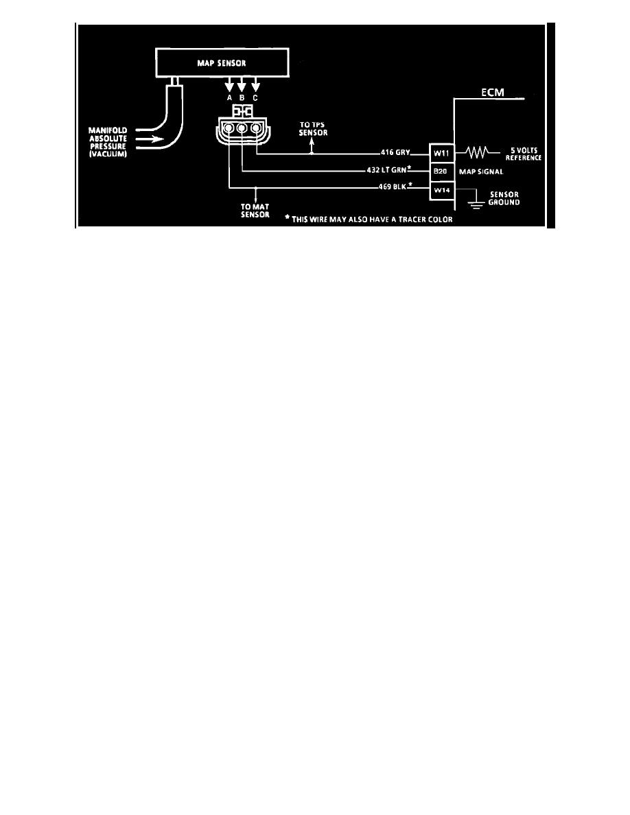
Fig. 006 - Wiring Diagram for the Chart C-1D MAP Output Check. VIN U
CHART C-1D-1
MAP OUTPUT CHECK
2.0L (VIN K)
2.5L (VIN R) (VIN U)
FUEL INJECTION (TBI)
Circuit Description: The Manifold Absolute Pressure Sensor (MAP) measures manifold pressure (vacuum) and sends that signal to the ECM. The
MAP Sensor is mainly used for fuel calculation, when the ECM is running in the throttle body backup mode. The MAP Sensor is also used to determine
the barometric pressure and to help calculate fuel delivery.
Test Description: Numbers below refer to circled numbers on Diagnostic Chart
1.
Checks MAP sensor output voltage to the ECM. This voltage, without engine running, represents a barometer reading to the ECM.
2.
Apply 34 kPa (10" Hg) vacuum to the MAP sensor should cause the voltage to be 1.2 volts less than the voltage at Stop 1. Upon applying vacuum
to the sensor, the change in voltage should be instantaneous. A slow voltage change indicates a faulty sensor.
3.
Check vacuum hose to sensor for leaking or restriction. Be sure no other vacuum devices are connected to the MAP hose.