
Electra V6-231 3.8L VIN C SFI (1988)
Data Link Connector: Description and Operation
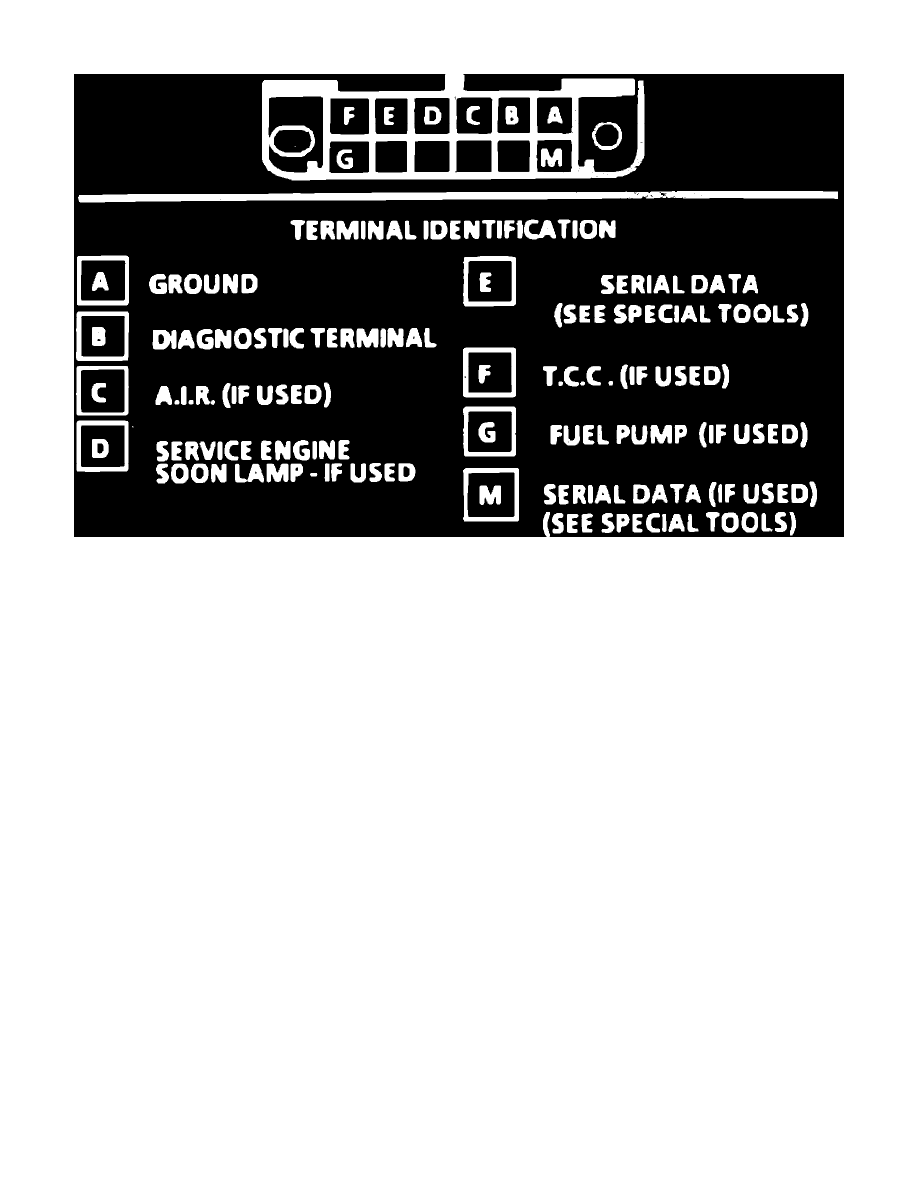
ALDL connector
To extract a trouble code from the ECM for diagnostic purposes, the Assembly Line Diagnostic Link (ALDL) connector, Fig. 6, is used. The ALDL
connector is located in the passenger compartment. Terminal B of the connector is the test terminal and terminal A is the ground used for diagnostic
display.
If the test terminal is grounded with ignition on and engine not running, the system will enter the diagnostic mode. In this mode, any stored trouble
codes will be displayed by flashing the CEL. In the diagnostic mode, the ECM will also energize all ECM controlled relays and solenoids. If the test
terminal is grounded with the engine running, the system will enter the field service mode. In this mode, the CEL will indicate whether the systems in
open or closed loop operation. If the system is in open loop operation, the lamp will flash approximately two and one-half times per second. Closed loop
operation is indicated by the lamp flashing approximately once per second. In closed loop operation, the lamp will stay out most of the time if system is
too lean and remain on most of the time if system is too rich.
The remaining terminals of the ALDL connector allow access to specific system circuit information. Terminals ``E'' or ``M,'' depending upon the
application, allow for the connection of SCAN type testers in order to read serial data. Serial data is a constant stream of information which relates all
current ECM sensor inputs and ECM commands to controlled devices. Reading this data allows the system to be monitored under actual operating
conditions, and aids in diagnosing system malfunctions.