Electra V6-260 4.3L DSL (1984)
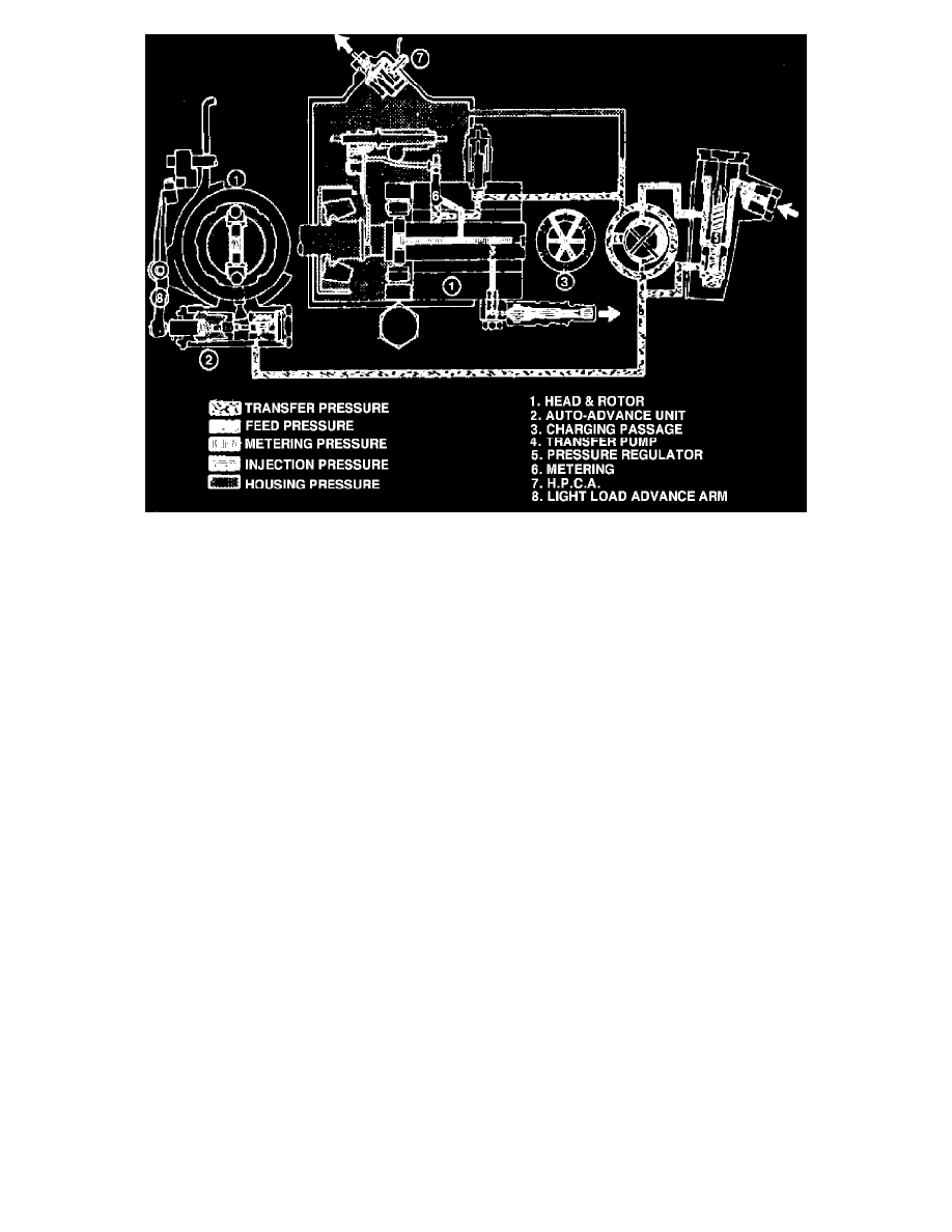
Fig. 39 CAV pump fuel flow schematic
The fuel flow schematics, Figs. 38 and 39, show the major components and their relationships and also provides a means of determining the
differences in the two systems.

Fig. 39 CAV pump fuel flow schematic
The fuel flow schematics, Figs. 38 and 39, show the major components and their relationships and also provides a means of determining the
differences in the two systems.