
Electra Park Avenue V6-231 3.8L VIN 3 FI (1988)
Valve Body: Service and Repair
CONTROL VALVE BODY 4T60 (440-T4)
1.
Disconnect battery ground cable.
2.
Disconnect vacuum hoses from cruise control servo unit, if equipped.
3.
Disconnect electrical connector from neutral/back-up lamp switch.
4.
Raise and support vehicle, then remove left front wheel.
5.
Remove inner splash shield.
6.
Disconnect left tie rod from steering knuckle using suitable puller.
7.
Disconnect stabilizer link from left control arm.
8.
Install drive axle boot seal protectors, as needed. Models using silicone (gray) boots on drive axle joints require the use of seal protectors
J-33162 or equivalent. Models using thermoplastic boots (black) do not require use of seal protectors.
9.
Disconnect ball joint from left steering knuckle.
10.
Disconnect left drive axle from transaxle, using suitable puller, and secure drive axle aside, taking care not to extend drive axle joints.
11.
Remove pinch bolt securing intermediate shaft to steering gear and disconnect intermediate shaft from gear.
12.
Position suitable jack under transaxle oil pan and raise jack until weight of transaxle is supported.
13.
Remove 3 bolts securing frame to body on left side.
14.
Lower transaxle just enough to gain access to side cover pan bolts.
15.
Disconnect cooler lines from transaxle and plug lines and open fittings.
16.
Remove side cover bolts, side cover and gaskets.
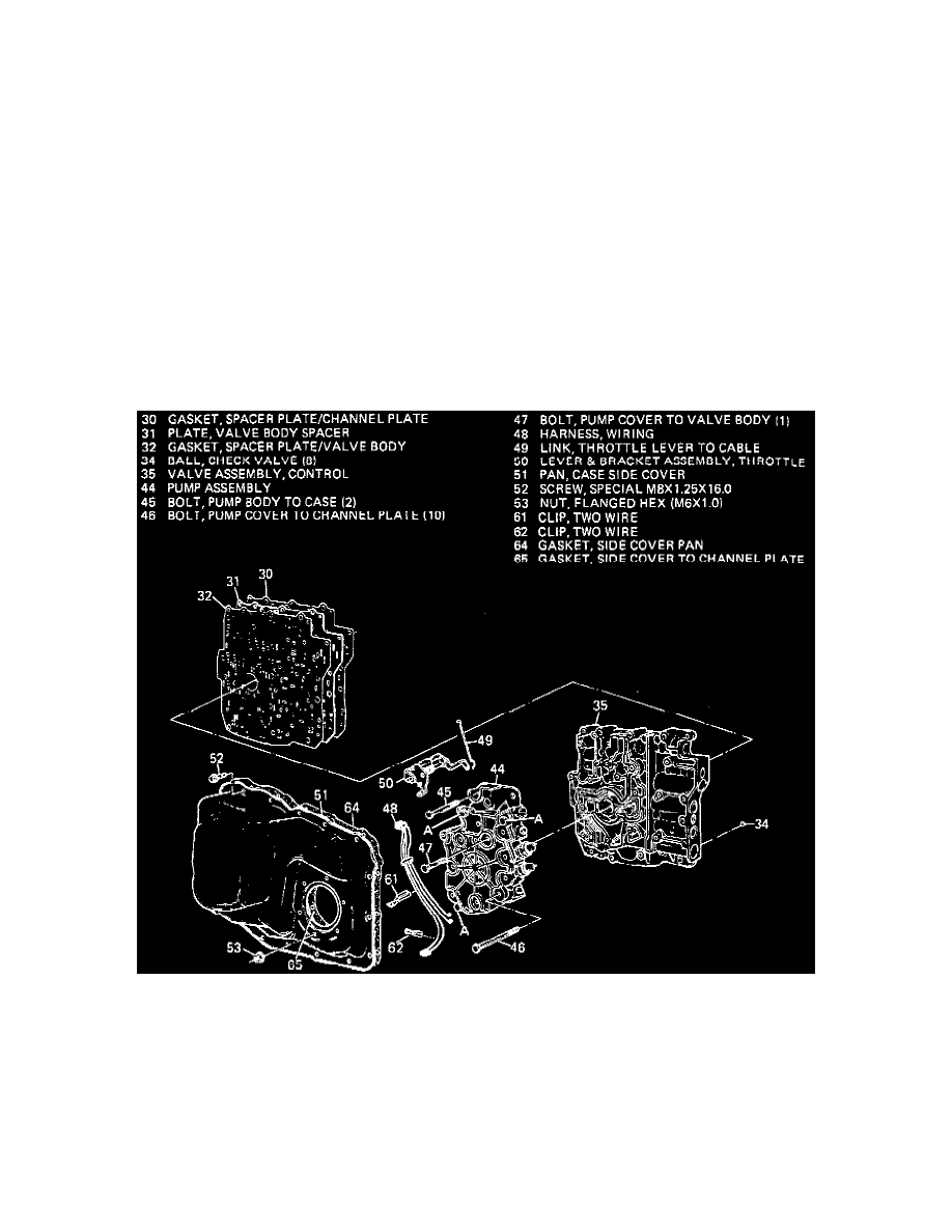
Fig. 4, Valve body assembly
17.
Remove valve body retaining bolts, valve body, oil pump and gaskets as an assembly, Fig. 4. Do not remove three No. 40 Torx bolts securing
oil pump together.
18.
Reverse procedure to install.