Electra Park Avenue V6-231 3.8L VIN 3 FI (1988)

Installing Armrest W/O Power Windows
NOTICE: When removing a door trim panel or switch plate, the ignition switch must be in the off position. This will eliminate the possibility of
shorting out the switch if a screwdriver, awl or metal object is used to remove the switch from the harness.
REMOVE OR DISCONNECT
1. Window regulator handle.
2. Screw (11) retaining outside mirror cover plate on all styles except the 6CD47-69 and 6CH23-33 styles.
3. Outside mirror cover plate on all styles except the 6CD47-69 and 6CH23-33 styles.
4. Screw (12) holding trim panel to inner panel behind cover plate on all styles except 6CD47 and 6CH23-33 styles.
5. Screws (13) at door pull handle.
6. Screw (14) holding inside remote handle cover plate to trim panel.
7. Inside remote handle cover plate by disconnecting all electrical connections.
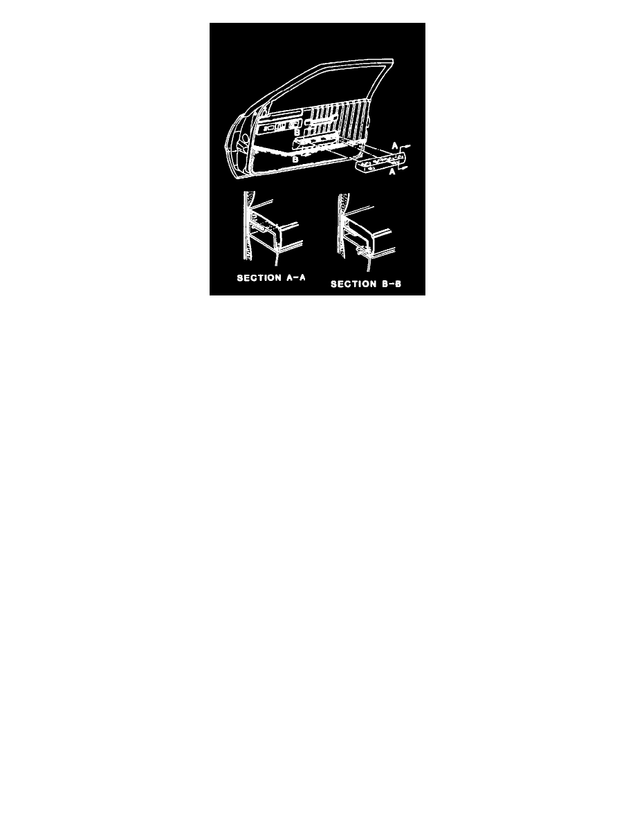
8. Rear courtesy lens of armrest.
^
6CD47-69 and 6CH23-33 styles (15) insert a thin-bladed screwdriver between top of lens and armrest and carefully press down to disengage
tabs on lens from armrest.
^
All other styles (16) - insert a thin-bladed screwdriver between sides of lens and press towards lens.
9. Screw (17) behind courtesy lens holding trim panel to door inner panel.
10. Lower courtesy lens (18) on 6CD47-69 and 6CH23-33 styles by following procedure outlined in step 8.
11. Screw (19) behind lower courtesy lens holding trim panel to door inner panel.
12. Switch plate assembly on armrest of front doors (except 3CX69 and 3CW69 style right front door which uses procedure outlined in step 13), by
placing a flat-bladed screwdriver into access slot at rear of switch plate and carefully pushing forward and up to disengage retainers on switch
plate from armrest. Remove electrical connections (20) and outside mirror control handle if present. handle if present.
13. Switch plate on rear doors requires removal of ashtray and lighter, then remove screws (23) retaining plate assembly to armrest.
14. Electrical connections (20).
15. Switch plate.
16. Armrest pad on H style front door without power windows and all H style rear doors.
17. Screws (21) holding trim panel along top of armrest on 6CD47-69 and on H style front doors without power windows and all H style rear doors.
On 6CH23-33 styles, screw (22) facing down at base of armrest.
18. Trim panel by using tool BT-7323A or equivalent between trim panel fasteners and door inner panel to disengage fasteners on trim panel from
holes in inner panel.
INSTALL OR CONNECT
1. Fasteners to trim panel if broken or damaged during removal operation.
2. Trim panel to inner panel by aligning fasteners on trim panel to holes in inner panel. Using a clean rubber mallet, tap trim panel in place.
3. Screws (21) along top of armrest.
4. Armrest pad (Fig. 2) on H style front door without power window and all H style rear doors.
5. Screw (22) facing down at base of armrest of 6CD47-69 and 6CH23-33 styles.
6. Electrical connections (20) to switch plate.
7. Outside mirror control handle if present.
8. Switch plate.
