
Electra Park Avenue V8-307 5.0L VIN Y 4-bbl (1984)
- Wiring Diagram for Chart C-2C Stepped Speed Control (SSC) Power Steering Circuit Check.
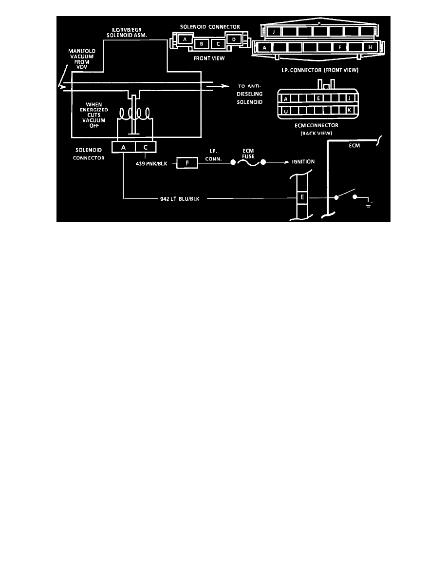
CHART C-2C, IDLE LOAD COMPENSATOR (ILC) CHECK (VIN Y)
CIRCUIT DESCRIPTION
The idle load compensator mounted on the carburetor is used to control throttle angle during long decelaration, such as coasting down a long grade,
and certain wide open throttle positions. The ILC uses a spring loaded vacuum sensitive diaphragm whose plunger extends with loss of vacuum to
increase idle speed. Vacuum is controlled by a vacuum solenoid which is ECM controlled. Battery voltage is supplied by ignition to the solenoid and the
ground is completed by the ECM to energize the ILC solenoid. When energized, the solenoid does not allow vacuum to go to the ILC, thus, extending
the ILC plunger to increase idle speed.
CHART DESCRIPTION
1.
Checks for normal ILC operation during idle. ILC should be retracted.
2.
By depressing TPS plunger, ILC should extend.
3.
Checks for the signal to energize the ILC solenoid. With the TPS depressed, the light should normally go "ON" if the circuit is OK.
4.
Checks to see if plunger remaining extended is due to an electrical failure of a grounded circuit including ECM, or faulty ILC vacuum or solenoid.
If the ILC and vacuum are OK, the ILC plunger will retract.
5.
Checks Anti-Diesel solenoid for supply of vacuum to ILC from vaccum tank on ignition shut down. Plunger should retract fully.
6.
Checks Anti-Diesel solenoid for blockage of vacuum from DVDV to ILC. With engine running solenoid should be energized and passing vacuum
from DVDV to ILC.