
Enclave AWD V6-3.6L (2009)
procedure.
Note:
*
Do NOT install used correction plates in an attempt to correct brake rotor assembled LRO.
*
Do NOT stack up, or install more than one correction plate onto one hub/axle flange location, in an attempt to correct brake rotor assembled
LRO.
6. Install the correction plate (1) onto the hub/axle flange, with the V-shaped notch (2) orientated to align with the high spot mark (3), that was
positioned to face upward.
7. Install the brake rotor to the hub/axle flange. Use the matchmark made prior to removal for proper orientation to the flange.
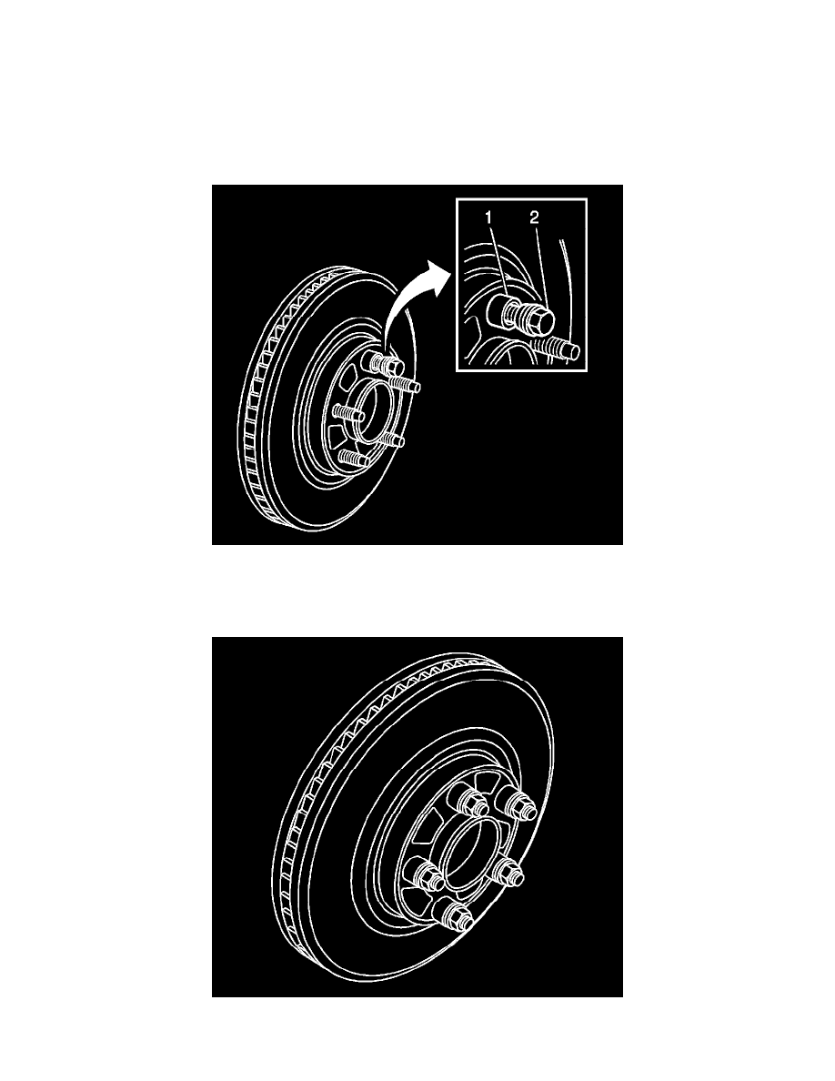
8. Hold the rotor firmly in place against the hub/axle flange and install one of the J-45101-100 - washers (1) and one lug nut (2) onto the upper-most
wheel stud.
9. Continue to hold the rotor secure and tighten the lug nut firmly by hand.
10. Install the remaining J-45101-100 - washers and lug nuts onto the wheel studs and tighten the nuts firmly by hand in a star-pattern.
11. Using the J-39544-KIT - set , or equivalent, tighten the lug nuts in a star-pattern to specification, in order to properly secure the rotor. Refer to