
Enclave FWD V6-3.6L (2008)
Variable Induction Control Valve: Description and Operation
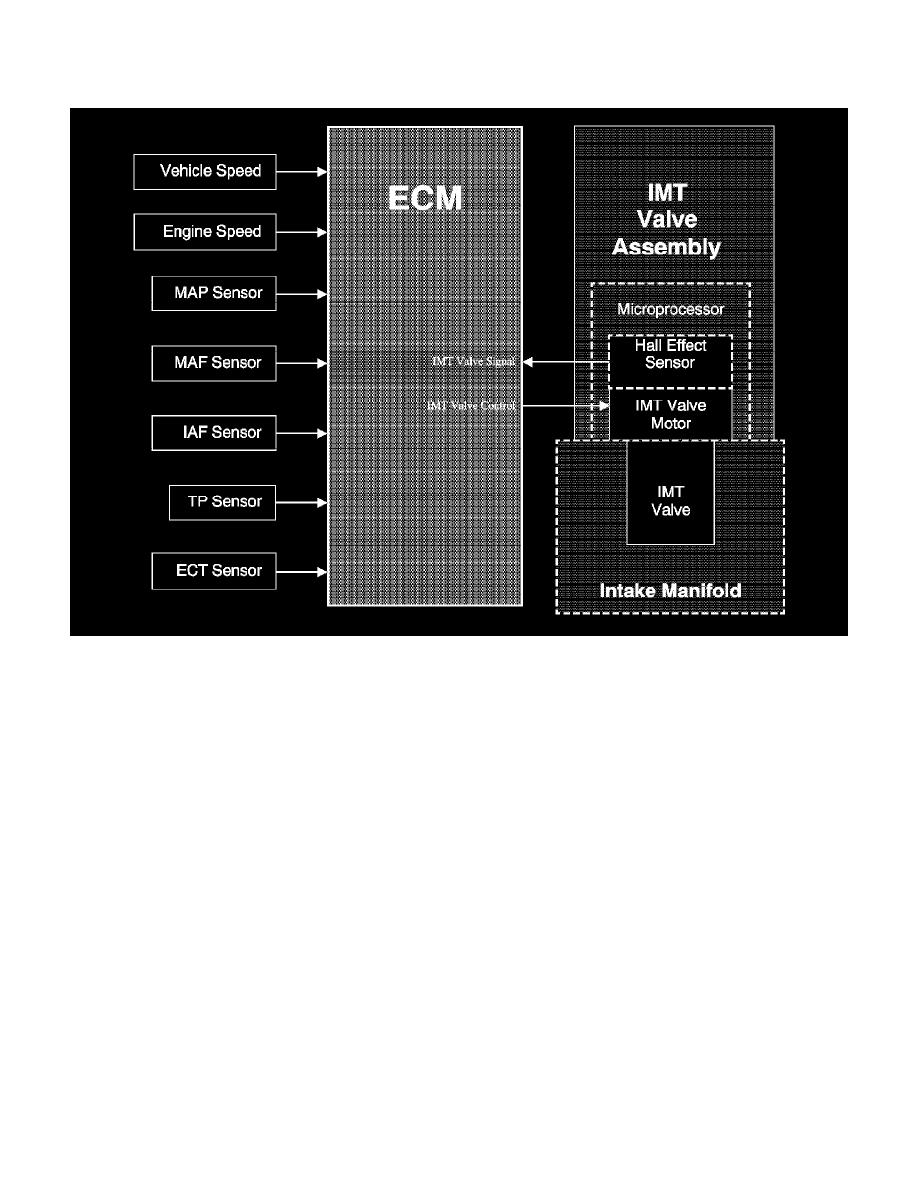
Intake Manifold Tuning Valve System Description
Intake Manifold Tuning (IMT) Valve System
The intake manifold tuning (IMT) valve system uses variable air induction tuning in order to achieve maximum performance and efficiency over the
entire operating range of the engine. The characteristic torque curve of a normally aspirated engine depends mainly on how the engines average pressure
changes over the engine speed range. The average pressure is proportional to the volume of the air mass present in the cylinder when the inlet valve is
closed. The design of the inlet system determines how large an air mass can be drawn into a cylinder at a given engine speed. An IMT valve is used to
change the intake manifold plenum configuration. When the IMT valve is open, the intake manifold is configured to one large plenum. When the IMT
valve is closed, the intake manifold is configured to 2 smaller plenums. The 2 intake manifold plenum sizes result in different torque curves, which
improves performance at low and high engine speeds. During low speed, high load conditions the IMT valve is closed creating a longer runner path
inside the plenum, which increases torque. During higher engine speeds and loads, the IMT valve opens creating a shorter runner path inside the plenum,
which increases horsepower.
Ignition Voltage and Ground
Ignition voltage and ground are supplied to the IMT valve microprocessor and motor.
IMT Valve Control Circuit
During operation when the valve is open, the control module applies ground to the IMT valve control circuit, which indicates to the microprocessor
within the IMT valve to position the valve to the closed position, which turns the motor ON and rotates the IMT valve within the intake manifold
plenum.
IMT Valve Signal Circuit
When the IMT valve is rotated, the hall-effect sensor is reporting the position of the valve to the microprocessor. The microprocessor then sends a
frequency back to the engine control module (ECM). The ECM uses this feedback signal to determine the position of the IMT valve.
Typical Scan Tool Data