
Enclave FWD V6-3.6L (2008)
12. Verify the key position for inserting the lock into the column.
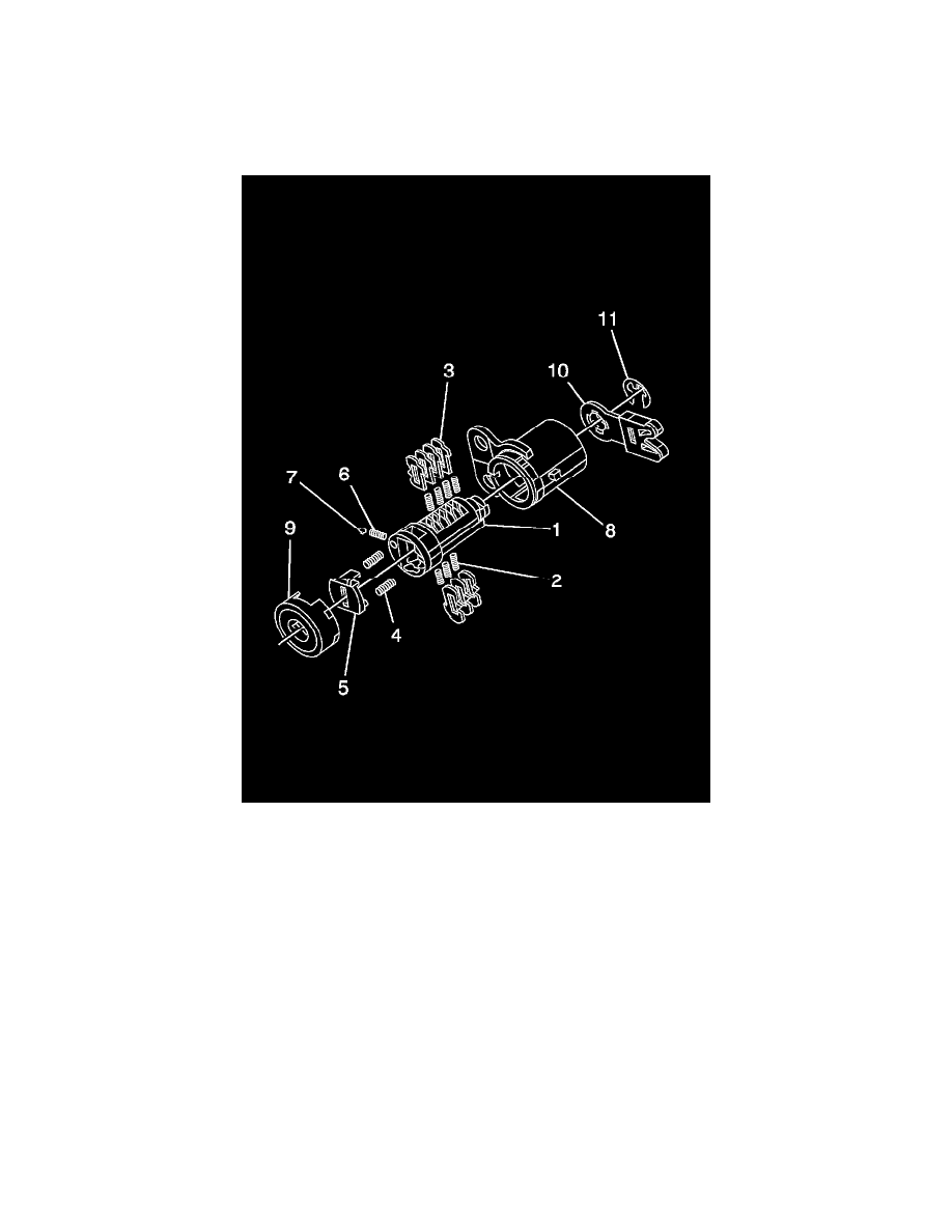
Door Lock Cylinder
The door lock cylinder only uses 7 of the 10 cut positions, 4 through 10. The tumbler positions are staggered from side to side, 4 on one side and 3 on
the other are self-retaining. The left and right door lock cylinders are identical. The lever assembly determines which side of the vehicle the lock cylinder
is for. After removing the current lock, record which lever is used and the orientation of the rod clip.
1. Rotate the cylinder (1) so the side with the 4 tumblers spring wells faces up.
2. Insert the tumblers springs (2) into the 4 spring wells.
3. Install the tumbler (3) for key cut position 4 in the slot closest to the cylinder head. Install the remaining tumblers, key cut positions 6, 8, 10,
following the key code and same process. Press tumblers in place until they are secure.
4. Check the correct loading of the tumblers by inserting the key into the cylinder. All tumblers should be flush with the lock cylinder body.
5. Turn the cylinder so the side with the 3 tumblers spring wells faces up.
6. Insert the tumbler springs into the 3 spring wells.
7. The first tumbler closest to the front of the lock cylinder to be loaded will be the fifth key cut position. Install the remaining tumblers for the key
cut positions 7 and 9. Press tumblers in place until they are secure.
8. Check the correct loading of the tumblers by inserting the key into cylinder. All of the tumblers should be flush with the lock cylinder body.
9. Apply lubricant to cylinder body and tumbler surfaces along with a small amount in head of cylinder using the supplied grease.
10. Install 2 springs (4) into the spring wells in head section of lock cylinder.
11. Snap the shutter assembly (5) into the cylinder.
12. Place the detent spring (6) into the spring well located on side of cylinder.
13. Carefully place the detent ball (7) on detent spring. Depress the detent ball into the cylinder and assemble into case (8). Detent ball should rest in
case slot at front of case.
14. Align dimples of the cylinder cap (9) with the 4 recesses in the cap. Secure by pressing the cap into place with light hand pressure.
15. If required, assemble rod clip to lever (10) using the recorded lever information.
16. Assemble lever to lock. Use e-clip (11) to retain lever assembly.
17. Insert the key into the lock and function lock to check for proper assembly and smooth operation.