
Enclave FWD V6-3.6L (2008)
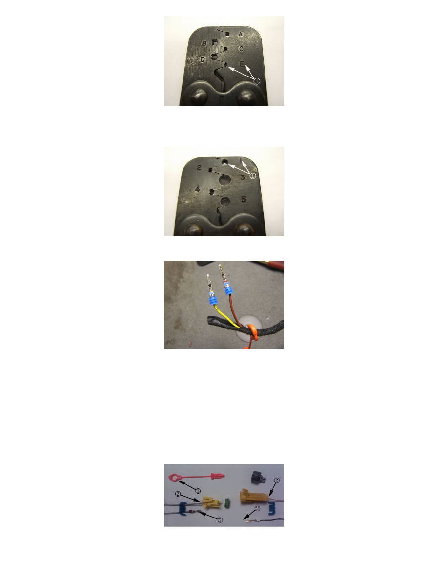
6. On the body harness, position two FEMALE terminals onto the wires. Caution must be used not to position the wire too far forward as it may
interfere with the mating portion of the terminal. Crimp the terminals on to the bare wire using the J- 38125-7 crimp tool, jaw E (1). Repeat the
procedure using two MALE terminals on the seat airbag harness.
7. Position the wire seal to the terminal and crimp the seal and insulation using the J-38125-6 crimp tool, jaw 1 (1).
The completed terminal and seal should appear as shown above (body harness connector shown).
Note
Avoid getting solder on the terminal end or overheating the terminal.
Warning
DO NOT use soldering equipment that is battery or electric powered. These types of soldering irons can induce voltage into the circuit, which may cause
inflator module deployment and/or damage to electrical components. Use only the EL-28125-5 Ultra Torch or another butane fueled soldering iron when
working on SIR circuits.
8. Solder all four terminals at the wire crimp.
9. Slide the two body harness terminals through the opening of the orange connector position assurance (CPA) (1).
Note