
Enclave FWD V6-3.6L (2008)
Ignition Switch Lock Cylinder: Procedures
Key and Lock Cylinder Coding
Ignition Lock Cylinder
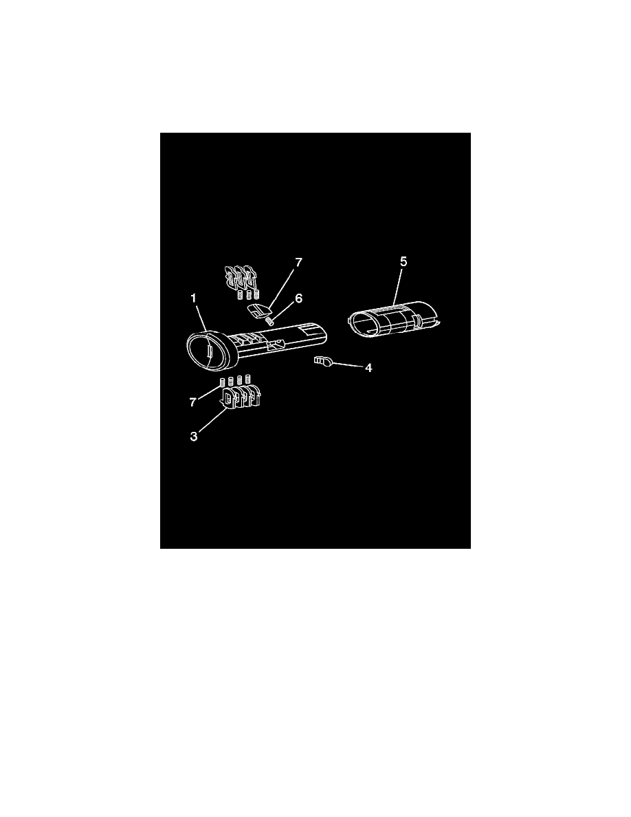
The ignition lock cylinder uses only 7 of the 10 cut positions, 2 through 8. The ignition cylinder tumblers (3) are located on alternate sides of the cylinder
(1). They are snap-in and self-retaining. It follows the key code with the first tumbler being the first depth of the key code, closest to the head of the key.
1. Hold the ignition cylinder assembly (1) so the side with the tumbler spring pocket located closest to the head of the cylinder is facing up.
2. Insert the tumbler spring (2) into each of the 4 spring pockets of the cylinder assembly.
3. The first tumbler (3) to be loaded will be the second key cut position, which is the second number in the key code. Install the first tumbler in the
slot over the spring. Install the remaining tumblers for cuts 4, 6, and 8 following the key code and same process, pressing the tumblers in place
until they are secure.
4. Rotate the cylinder assembly. Insert the tumbler spring into each of the spring pockets of the cylinder assembly.
5. The first tumbler to be loaded will be the third key cut position, the third number in the key code. Install the first tumbler in the slot over the
spring. Install the remaining tumblers for cuts 5 and 7 following the key code and same process, pressing the tumblers in place until they are
secure.
6. Inspect for correct loading of the tumblers by inserting the key into the cylinder. All tumblers should drop flush with the lock cylinder body
diameter.
7. Lightly lubricate the outside surface in the tumbler area of the lock body and down the key slot using the provided grease. Insert and extract the
key 5 times to lubricate the keyway.
8. With the key in the cylinder assembly, insert the actuator (4) in the actuator pocket and hold. Rotate the cylinder assembly and insert the retainer
spring (6) in the retainer slot located in the cylinder assembly. Insert the retainer (7) lining it up in the slot over the spring. Depress the retainer and
hold.
9. Insert the cylinder into the sleeve (5) as shown in the print. Make sure the actuator stays located properly in the cylinder.
10. When the key is removed, the lock should stay together.
11. Insert the key and function the lock 3 times to distribute the grease inside the sleeve.