
LaCrosse V6-3.6L (2007)
Variable Valve Timing Actuator: Service and Repair
First Design
CAMSHAFT POSITION ACTUATOR REPLACEMENT - BANK 1 (RIGHT SIDE) EXHAUST - FIRST DESIGN
Special Tools: EN 46108 Timing Chain Retention Tool
Important: To identify a camshaft drive design, refer to Camshaft Timing Drive Design Identification. See: Timing Components/Timing Component
Alignment Marks/Locations
Removal Procedure
1. Remove the lower intake manifold. See: Intake Manifold/Service and Repair
2. Remove the right camshaft cover. See: Cylinder Head Assembly/Valve Cover/Service and Repair
3. Remove the right intake and exhaust camshaft position sensors. See: Powertrain Management/Computers and Control Systems/Camshaft Position
Sensor/Service and Repair
4. Remove the right intake and exhaust camshaft position actuator solenoids. See: Variable Valve Timing Solenoid/Service and Repair
Important: Rotate the crankshaft balancer in a clockwise rotation ONLY.
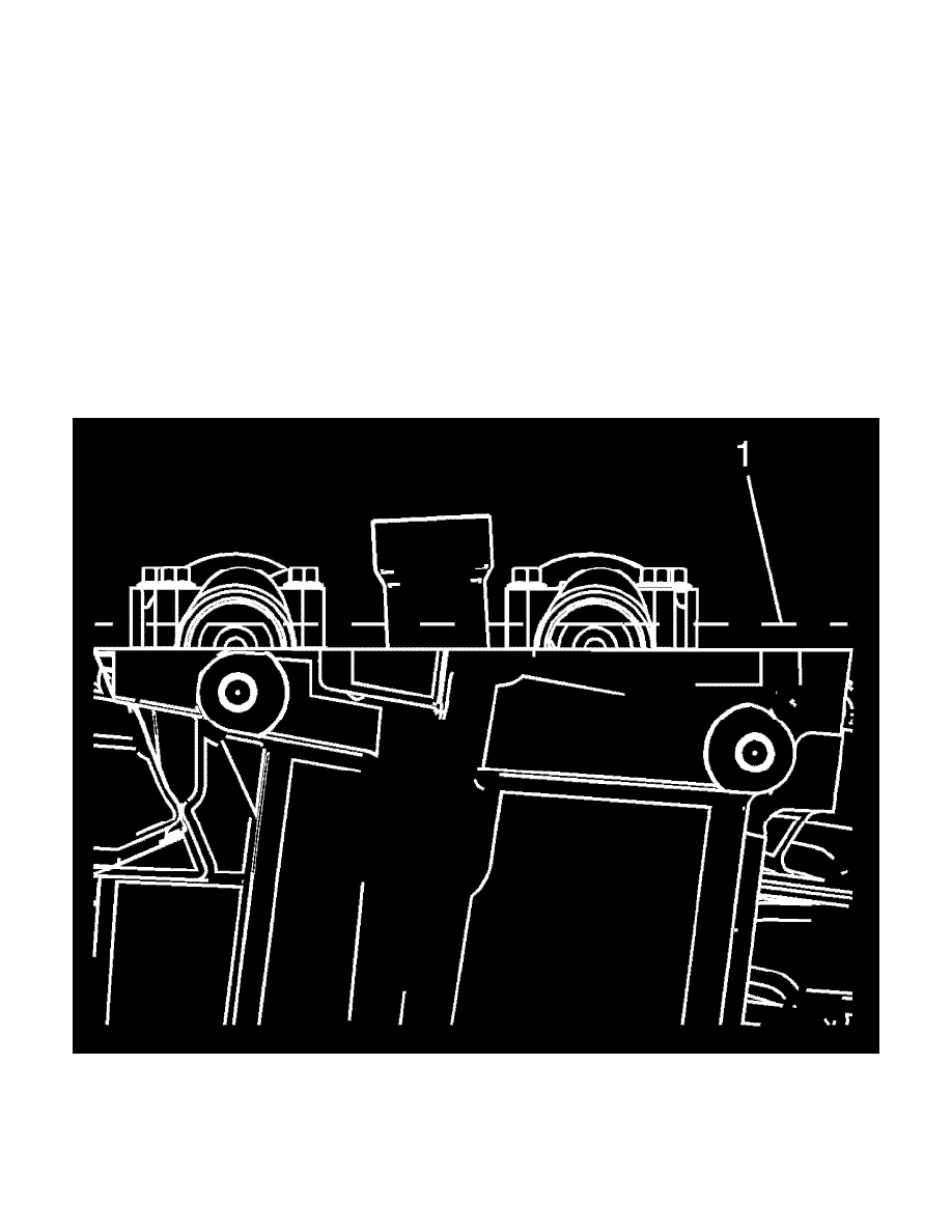
5. Rotate the crankshaft using the crankshaft balancer bolt until the camshafts are in a neutral (low tension) position. The camshaft flats will be
parallel with the camshaft cover rail (1).
Notice: A wrench must be used on the hex of the camshaft when loosening or tightening in order to prevent component damage. Failure to prevent