
LaCrosse V6-3.6L (2007)
-
Set-up a dial indicator on the camshaft to be measured. Set the dial indicator to measure the axial movement of the camshaft. To minimize
measurement error, the dial indicator needs to be on the same axis as the camshaft. A magnetic mount can be placed on the frame rail or a piece of
steel plate can be bolted to the top of the head as a reference surface for the dial indicator. The dial indicator should have 0.1 mm (0.001 in) of
resolution.
-
Position a screwdriver or small pry bar between the camshaft cap and camshaft lobe. Apply force to move the camshaft rearward.
-
Be cautious not to damage the camshaft lobe while applying this force.
-
Zero the dial indicator.
-
Apply force to move the camshaft forward (towards the camshaft phasers).
-
Read the dial indicator. This is the end play of the camshaft shaft.
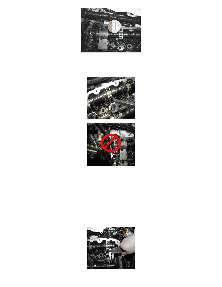
Notice
Do not use the phaser bolt as a pry point. This may cause damage to the camshaft sensor target wheel or the head to camshaft cover sealing surface.
Method 2: Caliper
The caliper should have 0.1 mm (0.001") of resolution.
-
Position a screwdriver or medium pry bar between the camshaft cap and camshaft lobe. Be cautious not to damage the camshaft lobe while