
LaCrosse V6-3.6L (2007)
Valve Body: Diagrams
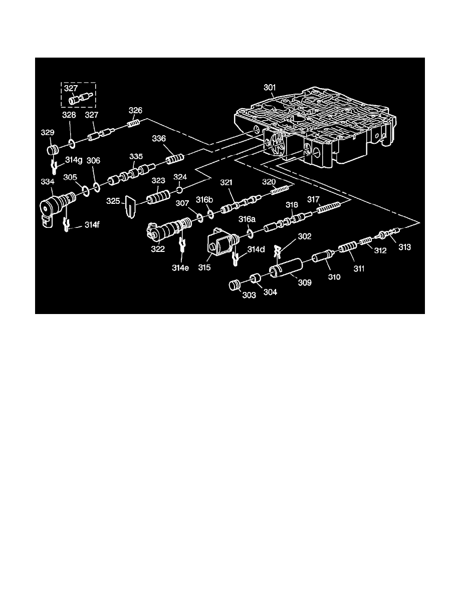
Control Valve Body Assembly
Control Valve Body Assembly - (1 of 2)
Control Valve Body Assembly
301 - Control Valve Body Machined
302 - Line Boost Valve and Bushing Retainer
303 - Line Boost Valve Bore Plug
304 - Line Boost Valve
305 - TCC PWM Solenoid Valve O-Ring Seal
306 - TCC PWM Solenoid Valve O-Ring Seal
307 - Pressure Control Solenoid Valve O-Ring Seal
309 - Reverse Boost Valve Bushing
310 - Reverse Boost Valve
311 - Pressure Regulator Valve Spring Outer
312 - Pressure Regulator Valve Inner Spring
313 - Pressure Regulator Valve
314d - 1-2, 3-4 Shift Solenoid Valve Retainer
314e - Pressure Control Solenoid Valve Retainer
314f - TCC PWM Solenoid Valve Retainer
314g - TCC Regulator Apply Valve Bore Plug Retainer
315 - 1-2, 3-4 Shift Solenoid Valve Assembly
316a - 1-2, 3-4 Shift Solenoid Valve O-Ring Seal
316b - Pressure Control Solenoid Valve O-Ring Seal
317 - 1-2 Shift Valve Spring
318 - 1-2 Shift Valve
320 - Torque Signal Regulator Valve Spring
321 - Torque Signal Regulator Valve
322 - Pressure Control Solenoid Valve Assembly
323 - Line Pressure Relief Valve Spring
324 - Line Pressure Relief Valve
325 - Line Pressure Relief Valve Spring Retainer