
LaCrosse V6-3.6L VIN 7 (2006)
Front Subframe: Service and Repair
Frame Replacement
Tools Required
J 39580 Universal Engine Support Table
Removal Procedure
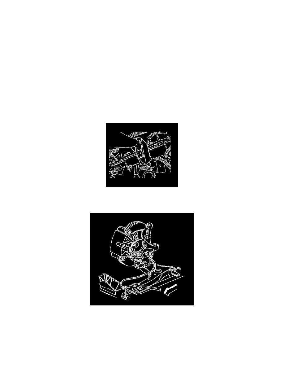
1. Install the engine support fixture.
2. Raise and support the vehicle. Refer to Vehicle Lifting.
3. Remove the front tires and wheels.
4. Remove and discard the two plastic braces from the front of the radiator lower air deflector. The plastic braces are directly below the front cradle
bolts.
5. Remove the positive battery cable and the retainers from the frame and position aside.
6. Disconnect the power steering return hose from the frame.
7. Secure the power steering return hose.
8. Remove the stabilizer shaft links and rotate the stabilizer shaft upward to gain access to the mounting bolts in the power steering gear.
9. Remove the mounting bolts from the power steering gear.
10. Secure the power steering gear.
11. Remove the nuts that secure the engine mount to the frame.
12. Remove the nuts which secure the transaxle mount to the frame.
13. If applicable, disconnect the front wheel speed sensor harness connectors.
14. If applicable, disconnect the wheel speed sensor harness from the frame and lower control arms.
15. If applicable, remove the retainers at the front wheel speed harness from the frame and from the lower control arms.
16. Separate both of the lower ball joints from the steering knuckle. Refer to Lower Control Arm Replacement in Front Suspension.
17. Remove both front drivetrain reinforcements using the following procedure.
1. Remove the drivetrain reinforcement to support brace bolts.
2. Remove the drivetrain reinforcement to front cradle mounting stud nut.