
LaCrosse V6-3.8L (2009)
Ignition Switch Lock Cylinder: Procedures
Key and Lock Cylinder Coding
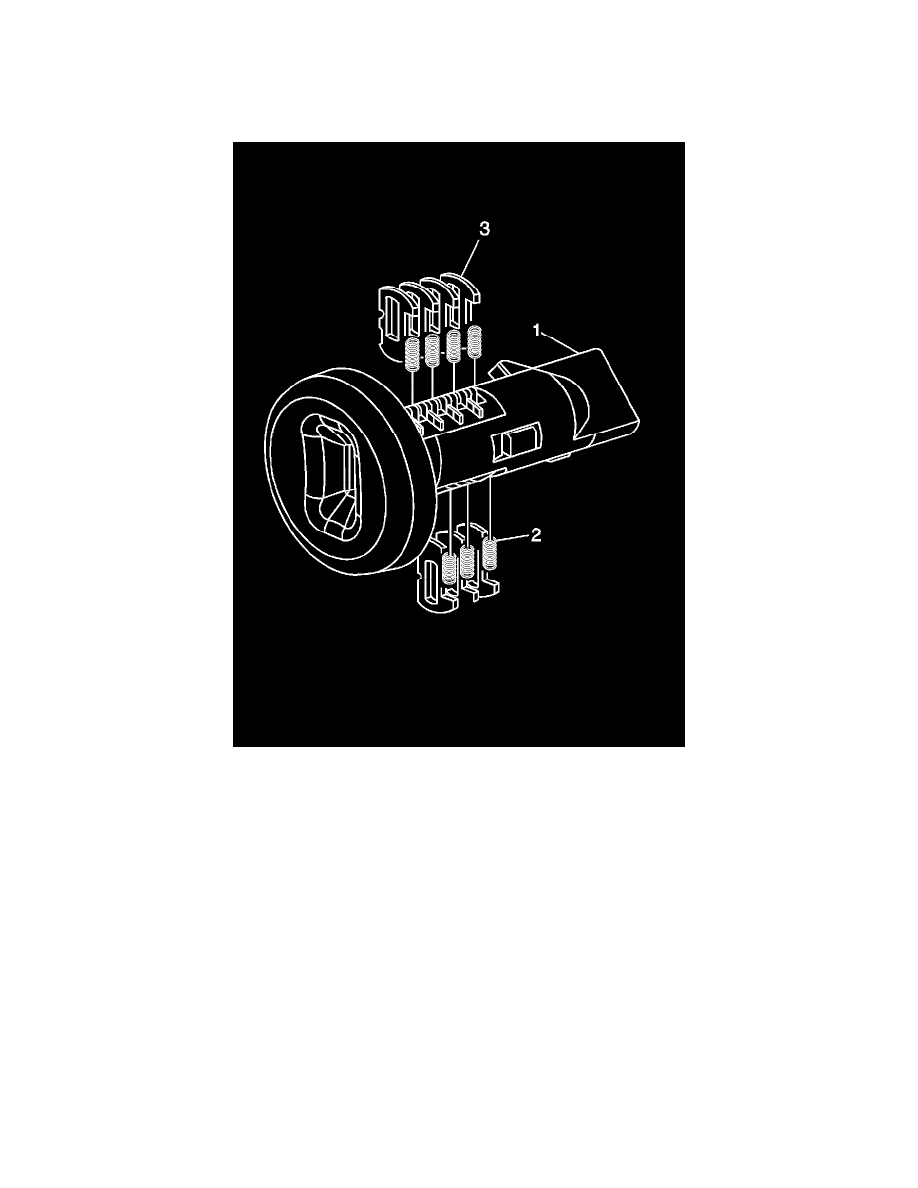
Ignition Lock Cylinder
The ignition lock cylinder only uses 7 of the 10 cut positions, 2 through 8. The ignition cylinder tumblers (3) are located on alternate sides of the cylinder
(1). They are snap-in and self-retaining. It follows the key code with the first tumbler being the first depth of the key code, closest to the head of the key.
Note: All lock cylinders for side milled keys have right and left tumblers. The location of the tooth of the tumbler determines whether it is right of
left. Illustrations in this procedure show the right tumblers on the top and the left tumblers on the bottom. All tumblers are marked 1R, 1L, 2R, or
2L. The number being cut depth and the letter meaning right or left.
1. Hold the ignition cylinder assembly (1) so that the side with the tumbler spring pocket located closest to the head of the cylinder is facing up.
2. Insert the tumbler springs (2) into each of the 4 spring pockets of the cylinder assembly.
3. The first tumbler (3) to be loaded will be the second key cut position, the second number in the key code. Install the first tumbler in the slot over
the spring. Install the remaining tumblers for cuts 2, 4, 6, and 8 following the key code and the same process. Pressing the tumblers in place until
they are secure.
4. Rotate the cylinder assembly. Insert the tumbler spring into each of the spring pockets of the cylinder assembly.
5. The first tumbler (3) to be loaded will be the third key cut position, the third number in the key code. Install the first tumbler in the slot over the
spring. Install the remaining tumblers for cuts 5, 7, and 9 following the key code and the same process. Pressing the tumblers in place until they are
secure.
6. Inspect for correct loading of the tumblers by inserting the key into the cylinder. The side bar should drop flush with the lock cylinder body
diameter.
7. Lightly lubricate the outside surfaces in the tumbler area of the lock body and down the key slot using the provided grease. Insert and extract the
key 5 times to lubricate the keyway.
8. Line up the lock to the run position. Insert the lock in the steering column. Rotate the lock to key out position and remove the key. Insert the key
and rotate the lock 3 times to distribute the grease from the lock to the column housing inside diameter.