
LaCrosse V8-5.3L (2008)
1. If you are replacing the VCIM, record the 10-digit standard identification (STID) number and the 11-digit electronic serial number (ESN) from the
labels on the new module.
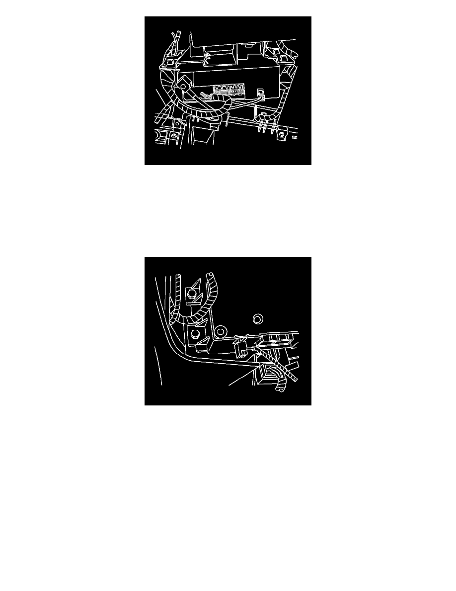
Notice: Before you install the antenna cable connector of the global positioning system (GPS) to the vehicle communication interface module
(VCM), align the connector properly in order to avoid damaging the connector.
2. Connect the navigation antenna coaxial cable to the module.
3. Connect the electrical connectors.
4. Connect the mobile telephone antenna cable to the module by pushing inward on the square plastic housing.
5. Align the module to the vehicle antenna module bracket.
Notice: Refer to Fastener Notice (See: Service Precautions/Vehicle Damage Warnings/Fastener Notice).
6. Install the communication interface module screws.
Tighten the screws to 2 N.m (18 lb in).
7. Install the HVAC module. Refer to Heater and Air Conditioning Control Replacement (See: Heating and Air Conditioning/Control
Assembly/Service and Repair).
8. Install the center console. Refer to Front Floor Console Replacement (See: Body and Frame/Interior Moulding / Trim/Console/Service and Repair
).
Important: After replacing the vehicle communication interface module, you must reconfigure the OnStar(R) system. Failure to
reconfigure the system will result in an additional customer visit for repair. In addition, pressing and holding the white dot button on the
keypad will NOT reset this version of the OnStar(R) system. This action will cause a DTC to set.
9. Reconfigure the OnStar(R) System. Refer to Control Module References (See: Testing and Inspection/Programming and Relearning) for