
LaCrosse V8-5.3L (2008)
12. Install the bolts to the HVAC module assembly upper support bracket.
Tighten the bolts to 4 N.m (36 lb in).
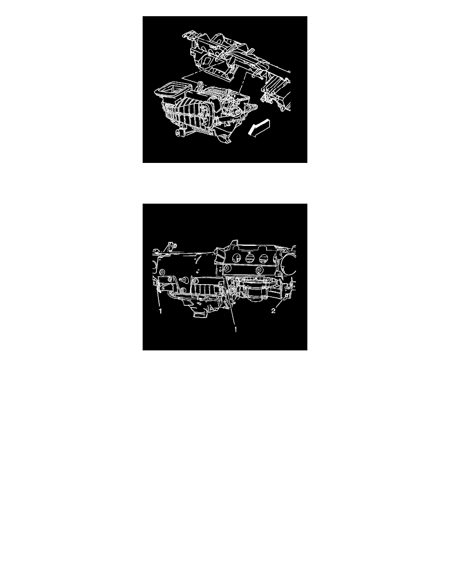
13. Install the bolts to the HVAC module assembly lower support bracket (1).
Tighten the bolts to 4 N.m (36 lb in).
14. Install the bolts to the HVAC module assembly RH support bracket (2).
Tighten the bolts to 4 N.m (36 lb in).
15. Position the I/P wiring harness to the original position.
16. Connect any disconnected ground wires.
17. Install the BCM.
18. Install the brake pedal brace bolts to the I/P carrier.
19. Install the brake pedal and the brake pedal bolt.
20. Install the booster push rod to the brake pedal.
21. Seat the bottom junction block tabs and snap the top of the junction block to the passenger knee bolster.
22. Install the junction block bolt.
Tighten the bolts to 10 N.m (89 lb in).
23. Install the I/P trim pad. Refer to Instrument Panel Trim Pad Replacement (See: Body and Frame/Interior Moulding / Trim/Dashboard / Instrument
Panel/Service and Repair).
24. Connect the battery negative cable. Refer to Battery Negative Cable Disconnection and Connection (L26) (See: Starting and
Charging/Battery/Battery Cable/Service and Repair)Battery Negative Cable Disconnection and Connection (LY7) (See: Starting and
Charging/Battery/Battery Cable/Service and Repair)Battery Negative Cable Disconnection and Connection (LS4) (See: Starting and