
LaCrosse V8-5.3L (2008)
Horn: Symptom Related Diagnostic Procedures
Horns Malfunction
Horns Malfunction
Diagnostic Instructions
*
Perform the Diagnostic System Check - Vehicle (See: Testing and Inspection/Initial Inspection and Diagnostic Overview/Diagnostic System
Check - Vehicle) prior to using this diagnostic procedure.
*
Review Strategy Based Diagnosis (See: Testing and Inspection/Initial Inspection and Diagnostic Overview/Strategy Based Diagnosis) for an
overview of the diagnostic approach.
*
Diagnostic Procedure Instructions (See: Testing and Inspection/Initial Inspection and Diagnostic Overview/Diagnostic Procedure Instructions)
provides an overview of each diagnostic category.
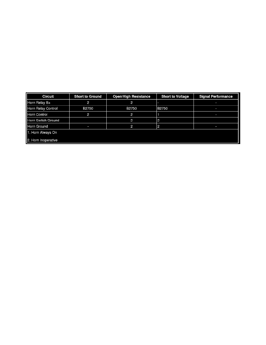
Diagnostic Fault Information
Circuit/System Description
Battery positive voltage is applied at all times to the horn relay coil and the horn relay switch. Pressing the horn switch applies ground through the switch
contacts and the horn relay control circuit to the coil side of the relay, energizing the relay. Battery voltage is then applied through the switch side of the
relay, the horn fuse, and the horn control circuit to the horns. The body control module (BCM) may also apply ground to the horn relay control circuit as
described above. The horns sound as long as ground is applied to the horn relay control circuit.
Diagnostic Aids
If diagnosing a Horn - Poor Tone condition, inspect the following:
*
Debris or water in the horn assembly.
*
Proper horn mounting hardware torque. Refer to Fastener Tightening Specifications (See: Specifications).
*
Debris in the joint where the horns attach to the vehicle.
Reference Information
Schematic Reference
Horn Schematics (See: Diagrams/Electrical Diagrams)
Connector End View Reference
Component Connector End Views (See: Diagrams/Connector Views)
Description and Operation
Horns System Description and Operation (See: Description and Operation)
Electrical Information Reference
*
Circuit Testing (See: Testing and Inspection/Component Tests and General Diagnostics)
*
Connector Repairs (See: Testing and Inspection/Component Tests and General Diagnostics)
*
Testing for Intermittent Conditions and Poor Connections (See: Testing and Inspection/Component Tests and General Diagnostics)
*
Wiring Repairs (See: Testing and Inspection/Component Tests and General Diagnostics)
Scan Tool Reference
Control Module References (See: Testing and Inspection/Programming and Relearning) for scan tool information
Circuit/System Verification