
LaCrosse V8-5.3L (2008)
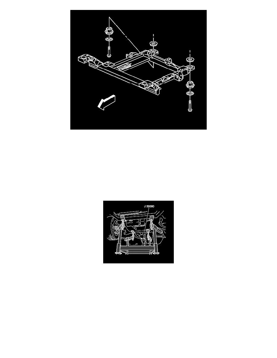
20. Remove the bolts which secure the rear frame to the body.
21. Raise the vehicle in order to separate the frame from the body.
22. If you are replacing the frame, remove the following components:
*
Both of the lower control arms-Refer to Lower Control Arm Replacement (See: Control Arm/Service and Repair).
*
The stabilizer shaft-Refer to Stabilizer Shaft Replacement (See: Stabilizer Bar/Service and Repair/Front Suspension).
*
The spacers, the upper insulator, the lower insulator, and the retainers-Refer to Front Frame Cushion or Insulator Replacement (See: Body and
Frame/Frame/Body / Frame Mount Bushing/Service and Repair/Front Frame Cushion or Insulator Replacement) or to Rear Frame Cushion or
Insulator Replacement (See: Body and Frame/Frame/Body / Frame Mount Bushing/Service and Repair/Rear Frame Cushion or Insulator
Replacement).
Installation Procedure
1. If you are replacing the frame, install the following components:
*
Both of the lower control arms-Refer to Lower Control Arm Replacement (See: Control Arm/Service and Repair).
*
The stabilizer shaft-Refer to Stabilizer Shaft Replacement (See: Stabilizer Bar/Service and Repair/Front Suspension).
*
The spacers, the upper insulator, the lower insulator, and the retainers-Refer to Front Frame Cushion or Insulator Replacement (See: Body and
Frame/Frame/Body / Frame Mount Bushing/Service and Repair/Front Frame Cushion or Insulator Replacement) or to Rear Frame Cushion or
Insulator Replacement (See: Body and Frame/Frame/Body / Frame Mount Bushing/Service and Repair/Rear Frame Cushion or Insulator
Replacement).
2. Position the engine support table with the frame under the vehicle.
3. Lower the vehicle to the frame.