
LaCrosse FWD L4-2.4L (2011)
Garage Door Opener Transmitter: Testing and Inspection
Garage Door Opener Malfunction
Diagnostic Instructions
*
Perform the Diagnostic System Check - Vehicle (See: Testing and Inspection/Initial Inspection and Diagnostic Overview/Diagnostic System
Check - Vehicle) prior to using this diagnostic procedure.
*
Review Strategy Based Diagnosis (See: Testing and Inspection/Initial Inspection and Diagnostic Overview/Strategy Based Diagnosis) for an
overview of the diagnostic approach.
*
Diagnostic Procedure Instructions (See: Testing and Inspection/Initial Inspection and Diagnostic Overview/Diagnostic Procedure Instructions)
provides an overview of each diagnostic category.
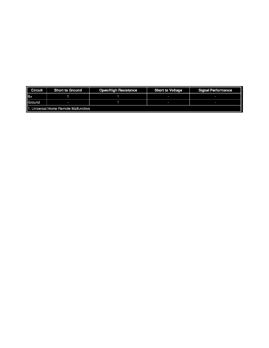
Diagnostic Fault Information
Circuit/System Description
The universal home remote is a transmitter operating between 288 and 434 MHz. The universal home remote has three buttons that may be programmed
for individual transmitter/receiver combinations to control up to three garage doors, security gates, lighting systems, etc. Each button represents a unique
transmitter code section, which operates independently of the other buttons, and may be considered a separate transmitter.
Reference Information
Schematic Reference
Remote Function Schematics (See: Antitheft and Alarm Systems/Keyless Entry/Keyless Entry Transmitter/Diagrams/Electrical Diagrams)
Connector End View Reference
Component Connector End Views (See: Diagrams/Connector Views/Connector End Views By Name)
Description and Operation
Garage Door Opener Description and Operation (See: Description and Operation)
Electrical Information Reference
*
Circuit Testing (See: Testing and Inspection/Component Tests and General Diagnostics/General Electrical Diagnostic Procedures/Circuit
Testing/Circuit Testing)
*
Connector Repairs (See: Testing and Inspection/Component Tests and General Diagnostics/General Electrical Diagnostic Procedures/Connector
Repairs/Connector Repairs)
*
Testing for Intermittent Conditions and Poor Connections (See: Testing and Inspection/Component Tests and General Diagnostics/General
Electrical Diagnostic Procedures/Circuit Testing/Testing for Intermittent Conditions and Poor Connections)
*
Wiring Repairs (See: Testing and Inspection/Component Tests and General Diagnostics/General Electrical Diagnostic Procedures/Wiring
Repairs/Wiring Repairs)
Special Tools
J 41540 Universal Home Remote Tester
Circuit/System Testing
1. Ignition OFF, disconnect the harness connector at the S25 garage door opener.
2. Ignition OFF, test for less than 5 ohm between the ground circuit terminal 3 and ground.
‹› If greater than the specified value, test the ground circuit for an open/high resistance.
3. Ignition ON, verify a test lamp illuminates between the B+ circuit terminal 1 and ground.
‹› If the test lamp does not illuminate, test the B+ circuit for a short to ground or an open/high resistance.
Note: This step will clear any learned transmitters from the S25 garage door opener. This will require reprogramming by the customer to
reestablish universal home remote functionality.