
LaCrosse FWD L4-2.4L (2011)
Caution: For proper tool operation, a drill motor with a 1/2 inch chuck, 1 1/8 hp, 7 amps, triple gear reduction, and a 450-600 RPM rotational
speed in a clockwise direction must be used. If the proper drill motor is not used, damage to the cylinder bore sleeve will occur.
12. Fasten the drive adapter EN 45680-886 into the drill chuck.
Caution: Ensure that there are no crimps in the air feed hose or the vacuum hose. Crimps in the hose may cause metal shavings to exit the cutting
tool in any direction, causing engine damage.
13. Connect a compressed air supply (75-125 psi) to the male quick connect located on EN 45680-881 trim tool assembly. Turn the compressed air
valve to the open position. This starts the venturi vacuum system that will catch the metal shavings.
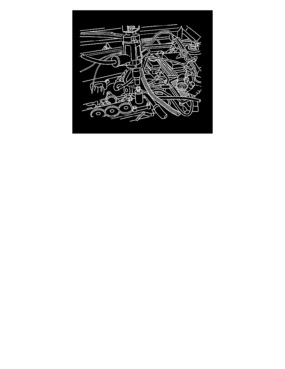
14. Place the EN 45680-886 drive adapter and the drill assembly vertically onto the EN 45680-881 drive adapter end of trim tool assembly. Do not
apply downward force on the drill until full rotational speed has been reached. After reaching full rotational speed, gradually apply downward
force until the cutting action is complete in approximately 5 seconds.
15. Remove the EN 45680-886 drive adapter (1) and the drill assembly from the EN 45680-881 trim tool assembly.
16. Turn OFF the compressed air valve.
17. Remove the EN 45680-881 trim tool assembly from the engine block.
18. Wipe the cylinder bore sleeve and the surrounding areas of any powder residue. Remove the EN 45680-883 metal shaving catch plug.