
LeSabre V6-231 3.8L VIN L SFI (1992)
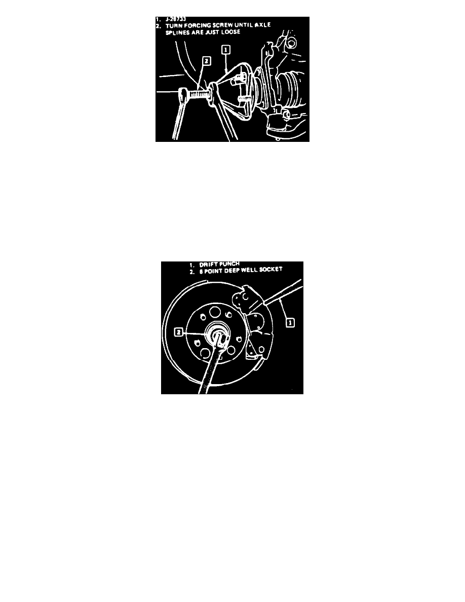
Fig. 8 Removing Drive Axle From Hub And Bearing Assembly
Removal
1.
Raise and support vehicle, then remove tire and wheel assembly.
2.
Install a brass drift or a screwdriver to prevent the rotor from turning, Fig. 7.
3.
Remove shaft nut and washer using shaft nut socket tool No. J-34826.
4.
Remove brake caliper from steering knuckle and suspend caliper assembly.
5.
Remove rotor from hub and bearing assembly, then stabilizer shaft or link from control arm.
6.
Remove ball joint from steering knuckle.
7.
Remove drive axle from transaxle using axle shaft remover tool No. J-33008, axle shaft remover tool No. J-29794 and slide hammer tool No.
J-2619-01 if necessary, Fig. 1.
8.
Remove drive axle from hub and bearing assembly using front hub spindle remover tool No. J-28733-A, Fig. 8.
Fig. 7 Removing And Installing Axle Shaft Nut
Installation
1.
Install drive axle into hub and bearing assembly and transaxle.
2.
Install lower ball joint to steering knuckle.
3.
Install stabilizer shaft or link to control arm.
4.
Install rotor to hub and bearing assembly.
5.
Insert a screwdriver or drift into caliper and rotor to prevent rotor from turning, Fig. 7.
6.
Install a new hub nut and washer, torque to 185 ft. lbs. On Cavalier, Celebrity, Century, Cutlass, Grand Am, LeSabre, Skyhawk, Skylark and
Sunbird. On Bonneville, Delta 88 and 98, Electra, LeSabre and Park Avenue models, torque to 192 ft. lbs.
7.
Seat the drive axle into the transaxle by placing a screwdriver into the groove on the joint housing and tapping until seated.
8.
Ensure drive axle is seated by pulling outward on the housing. Do not pull on the drive axle.
9.
Install tire and wheel assembly and lower vehicle.