
LeSabre V8-307 5.0L VIN Y 4-bbl (1984)
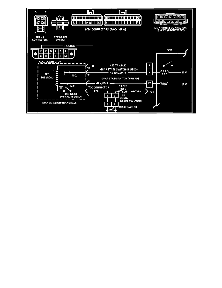
- Wiring Diagram for Chart C-8A-1 Transmission Converter Clutch.
CHART C-8A-1 TRANSMISSION CONVERTER CLUTCH (TCC) ELECTRICAL DIAGNOSIS
CHART DESCRIPTION
1.
Checks voltage from ignition switch through brake switch, 3rd gear apply switch (if used) and TCC Solenoid. Light should have turned on by 35
mph (56 km/h). Due to variations in specific TCC calibrations, it is possible to have a narrow margin between 3rd gear apply switch closing (if
used) and ECM grounding of TCC circuit from ECM terminal "P". Test light may turn "on" just momentarily within this margin.
2.
Checks to see if ECM completes ground to energize TCC solenoid. Light should go "OUT".
3.
Checks for open in circuits to terminals 'N' and '17'. The ECM supplies 12 volts to these terminals through a resistor. Normally both circuits should
have low voltage readings since they involve normally closed circuits with vehicle stopped. An open circuit would give a reading of about 12
volts.
4.
Switch(es) open when transmission up shifts. Checks that transmission circuit functions normally by voltage going high (near battery voltage) as
switches open.
5.
This increases throttle opening to increase TPS output. If TPS output is too low, the clutch won't apply. On some applications, running free doesn't
require enough throttle opening to allow the transmission to shift.
6.
Checks for low voltage at TPS input at ECM. At WOT, voltage should be approximately 5V (ref.). Too low a TPS output could prevent the
transmission from shifting.
7.
Checks for VSS signal at ECM. VSS signal is necessary to engage TCC.