
Lucerne V6-3.8L (2007)
Seat Heater: Symptom Related Diagnostic Procedures
Heated/Cooled Seats Inoperative Part 2
HEATED/COOLED SEATS INOPERATIVE
COMPONENT TESTING
Heated and Cool Seat Switch
1. Ignition OFF, disconnect the (C4) harness connector at the door module.
2. Test for infinite resistance between the following switch signal circuits and the low reference circuit terminal 4 with the switch in the open
position.
-
Terminal 7 heated seat back only mode switch signal
-
Terminal 6 heated seat back cushion heat switch signal
-
Terminal 3 heated seat cool switch signal
-
If less than infinite resistance, replace the heated and cooled seat switch.
3. Test for less than 2 ohms between the following switch signal circuits and the low reference circuit terminal 4 with the switch in the closed
position.
-
Terminal 7 heated seat back only mode switch signal
-
Terminal 6 heated seat back cushion heat switch signal
-
Terminal 3 heated seat cool switch signal
-
If greater than 2 ohms for any of the tests, replace the heated and cooled seat switch.
Ventilation Heat and Cool Module
1. Ignition OFF, disconnect the harness connectors at the seat cushion and seat back ventilation heat and cool modules.
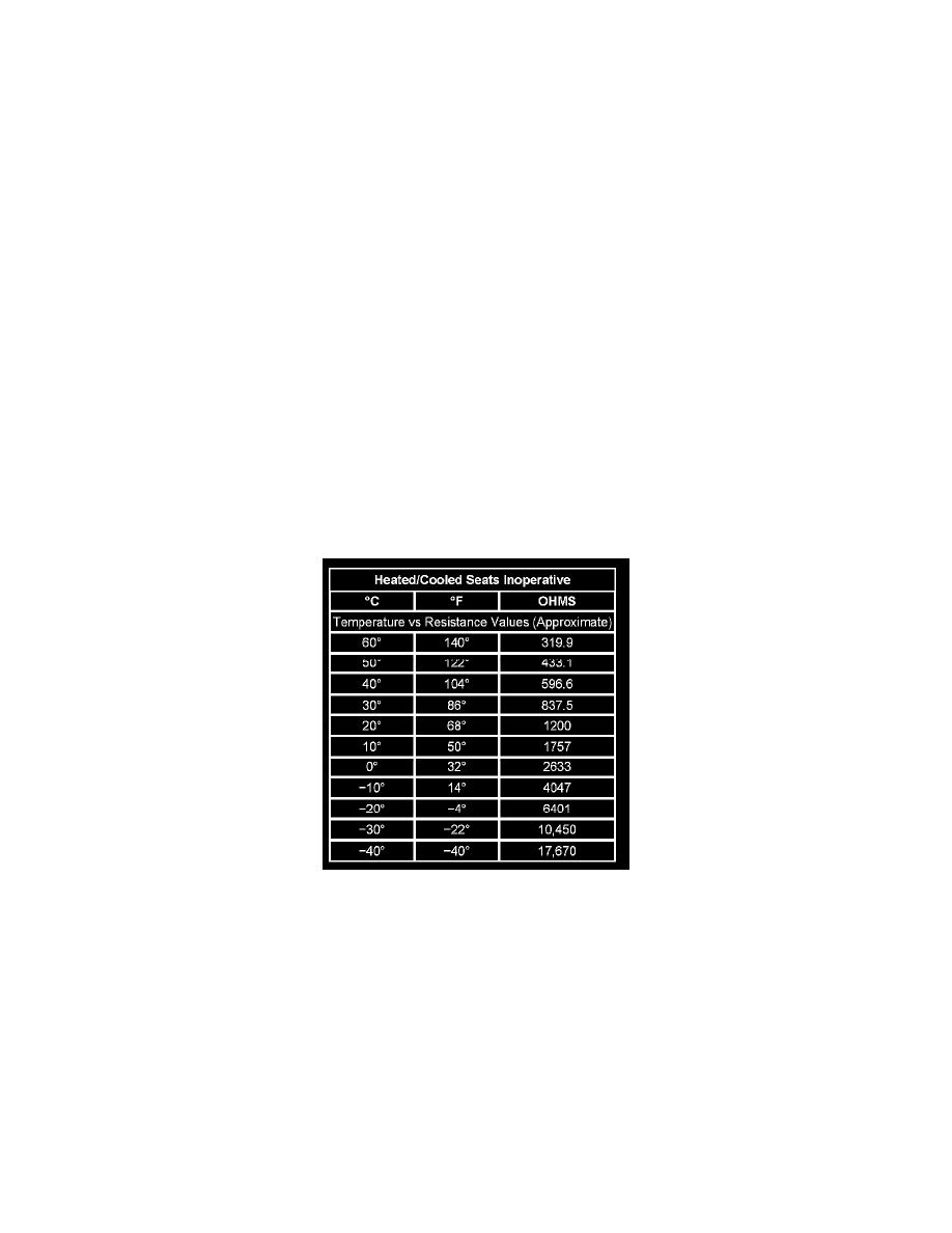
2. IMPORTANT: If the resistance is measured with the seat still warm or cool, the resistance values will vary. At 68°F (20°C), the nominal
resistance value is 1200 ohms ±5 percent. For hotter or colder ambient temperatures, refer to the Temperature vs Resistance table. The delta
resistance values between the seat cushion and seat back temperature sensors should not be greater than 2000 ohms.
Heated/Cooled Seats Inoperative
Test for 300 ohms - 18K ohms of resistance between the temperature sensor signal circuit terminal 5 and the low reference circuit terminal 8.
-
If the resistance is not within the specified range, replace the ventilation heat and cool module.
3. IMPORTANT: The test leads must be connected in the correct polarity, otherwise lower out of range values will appear. Use the Positive Lead
for the COOL control circuit and the Negative Lead for the HEAT control circuit. If the resistance is measured with the seat still warm or cool, the
resistance values will vary even if the system was powered up for just a few seconds. The TED must be allowed to stabilize to room temperature
prior to a measurement. The following conditions will change the resistance to out of range values:
-
The test leads are incorrectly connected
-
Air blowing across the TED.
-
Measuring the resistance at other than room temperature of 70°F.
-
Holding the TED portion of the heated and cool ventilation module in your hand.
In hotter or colder climates where room temperature conditions of 70°F (21°C) may be unattainable, resistance values may read above the
specified range. Use a heat gun or a blower to warm or cool the TED while measuring the resistance. The resistance values should slowly lower