
Park Avenue V6-231 3.8L VIN L SFI (1993)
ABS Main Relay: Customer Interest
ABS/Traction OFF MIL On, DTC's 45 or 61 (ABS Main Relay)
Group Ref.: Brakes
Bulletin No.: 435003
Date: May, 1994
SUBJECT:
FAULTY ABS MAIN RELAY OR ABS PUMP RELAY CAUSING ABS DIAGNOSTIC TROUBLE CODES (DTC'S) 45 OR 61
(DIAGNOSE/SERVICE PROCEDURE)
MODELS:
1991-94 BUICK LE SABRE AND PARK AVENUE
1991-94 OLDSMOBILE EIGHTY EIGHT AND NINETY EIGHT
1991-94 PONTIAC BONNEVILLE
CONDITION:
Some owners may comment that the "ABS" and, if equipped, "Traction Off" indicator lamps are on due to the presence of ABS Diagnostic Trouble
Codes (DTC's) 45 and 61.
CAUSE:
Either or both of the above DTC's could set due to a high contact resistance condition with the ABS main relay or the ABS pump relay.
CORRECTION:
Refer to bulletin # 335015 when diagnosing DTC 45 or bulletin # 315006R (previous divisional numbers were: T-93-97 - Cadillac; 93-5-124 - Canada;
93-T-71 - Oldsmobile; 93-5-14 - Pontiac) when diagnosing DTC 61 for 1991-1993 model year vehicles.
If the diagnostic procedure indicates that the EBCM/EBTCM or the Pressure Modulator Valve (PMV) should be replaced, the following relay test
should be performed first:
1.
Ignition to "off" position.
2.
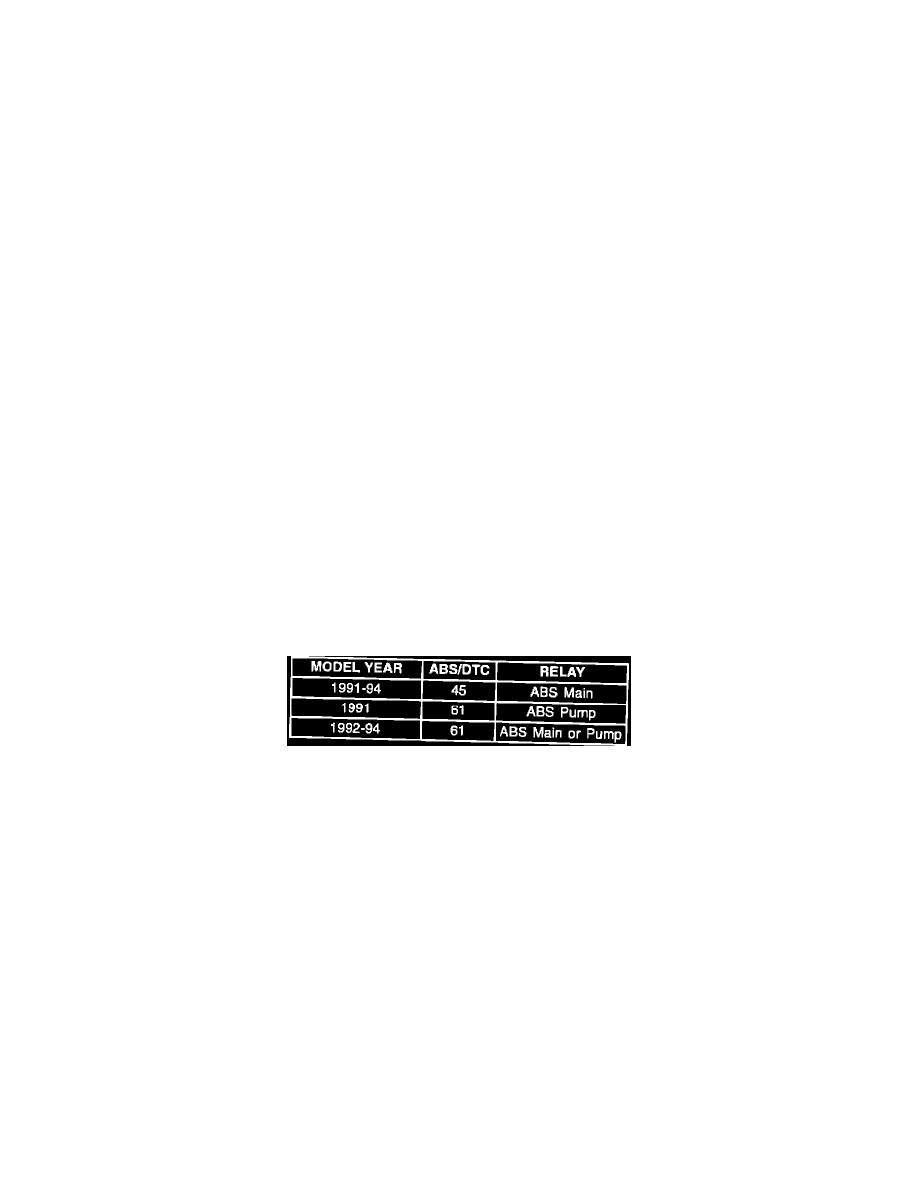
Remove appropriate relay determined by DTC and model year as follows:
3.
Using terminal repair tools from J 38125-A, remove relay harness connector terminals 1 and 4 (1991 - 1993) or 30 and 87 (1994) from relay
harness connector. DO NOT ATTEMPT TO PERFORM THIS TEST WITHOUT REMOVING THESE TERMINALS OR AN IMPROPER
RESISTANCE READING WILL BE MADE.
4.
Reinstall relay.
5.
Disconnect EBCM/EBTCM.
6.
Install J 38716 ABS Breakout Box.
7.
Using J 35616-A Connector Test Adaptor Kit, connect test leads from J 39200 Digital Multimeter to relay through open cavities in harness
connector.
8.
Set J 39200 to Ohm's scale.
9.
Ignition to the run position.
10.
Using a fused jumper, jump between breakout box terminals 1 and 34 for the ABS main relay or 1 and 15 for the ABS pump relay. Energize and
de-energize the relay at least ten times while monitoring relay contact resistance. If relay contact resistance exceeds 1 Ohm at any time, the relay
must be replaced.
11.
If relay tests okay, resume original diagnostic procedure. If relay is replaced, perform appropriate model year ABS or ABS/TCS functional test.
WARRANTY INFORMATION: