
Park Avenue V6-231 3.8L VIN L SFI (1993)
A/C Signal: Description and Operation
A/C Switch
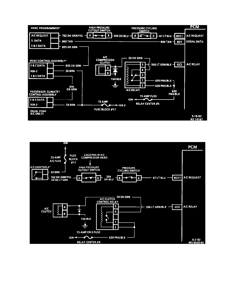
A/C Control Circuit Diagram (Electronic And Dual Zone A/C)
ELECTRONIC AND DUAL ZONE A/C
A/C Control Circuit Diagram (Manual A/C)
MANUAL A/C
The A/C switch applies battery voltage to the A/C request terminal of the PCM. The PCM then turns the A/C clutch relay "ON" and modifies the signal
to the idle air control valve to increase the idle speed. Increasing the idle speed is necessary to compensate for the added load on the engine and to ensure
efficient operation of the A/C system.