
Park Avenue V6-3.8L SC VIN 1 (2005)
12. Remove the left insulator panel.
13. Remove the CPA (1) from the steering wheel module coil yellow connector (4) located near the steering column (2).
14. Disconnect the steering wheel module coil yellow connector (4) from the vehicle yellow harness connector (3).
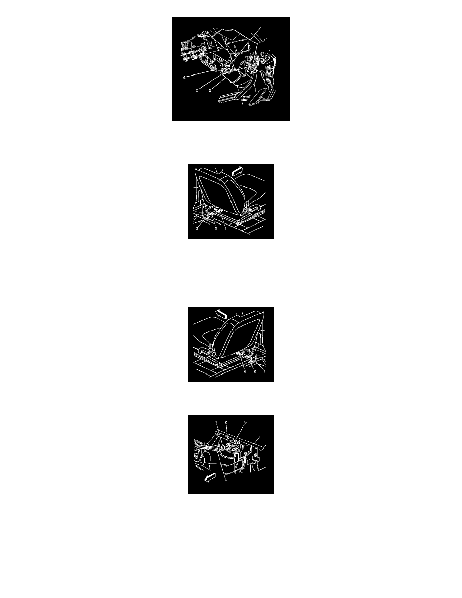
15. Remove the CPA (3) from the LF/driver side impact module yellow connector (1) which is located under the driver seat.
16. Disconnect the vehicle harness yellow connector (2) from the LF side impact module yellow connector (1).
ENABLING PROCEDURE
1. Remove the key from the ignition switch.
2. When enabling the RF/passenger seat, perform step 3 and step 4. If the SDM needs enabling, then use the entire procedure.
3. Connect the vehicle harness yellow connector (2) to the RF side impact module yellow connector (3).
4. Install the CPA (1) to the RF side impact module yellow connector (3).
5. Connect the I/P module yellow connector (1) to the vehicle harness yellow connector (2).
6. Install the CPA (4) to the vehicle harness yellow connector (2).
7. Install the right insulator panel.