
Park Avenue V6-3.8L SC VIN 1 (2005)
INSTALLATION PROCEDURE
NOTE: The IAC valve may be damaged if installed with the cone (pintle) extended more than 28 mm (1-1/8 in). Measure the distance that the valve
is extended before installing a new valve. The distance from the idle air control valve motor housing to the end of the idle air control valve pintle
should be less than 28 mm (1-1/8 in). Manually compress the pintle until the extension is less than 28 mm (1-1/8 in).
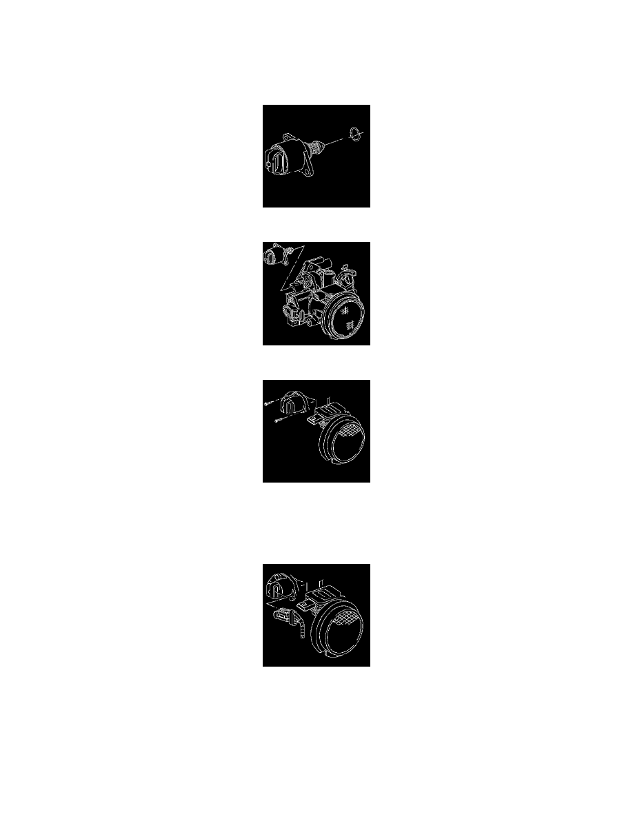
1. Install the new idle air control valve O-ring to the idle air control valve.
2. Install the idle air control valve into the throttle body.
3. Install the idle air control valve attaching screws.
NOTE: Refer to Fastener Notice in Service Precautions.
Tighten the bolts to 3 N.m (27 lb in).
4. Install the idle air control valve electrical connector to the idle air control valve.
5. The powertrain control module (PCM) will reset the idle air control valve whenever the ignition is turned ON, then OFF.Turn the ignition ON,
then OFF.
6. Start the engine and allow the engine to reach operating temperature.