
Park Avenue Ultra V6-3.8L SC VIN 1 (1991)
Engine Control Module: Service and Repair
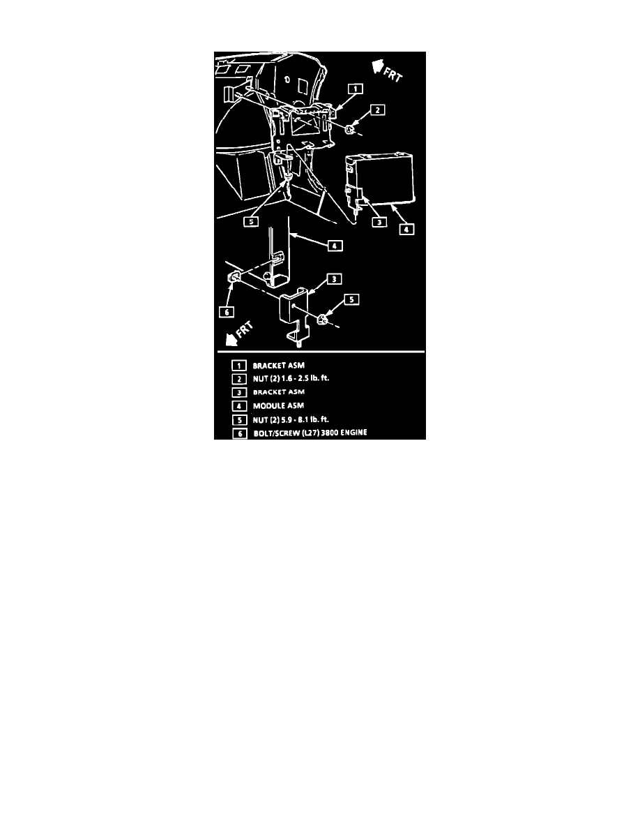
Computer
REMOVE OR DISCONNECT:
1.
Negative battery cable.
2.
Right hand hush panel.
3.
Connectors from the PCM.
4.
PCM mounting hardware.
5.
PCM from the passenger compartment.
6.
PCM access cover.
7.
MEM-CAL removal:
NOTE: The replacement PCM is not supplied with a MEM-CAL, so care should be used when removing it from the PCM, because it will be used
in the new PCM.
^
Using two fingers, push both retaining clips back away from the MEM-CAL. At the same time, grasp it at both ends and lift it up out of the
socket. DO NOT remove the cover of the MEM-CAL.
^
Note the position of the MEM-CAL for proper installation in the new PCM.
8.
New PCM from its packaging and check the service number to make sure it is the same as the defective one.
9.
access cover.
INSTALL OR CONNECT:
NOTE: Press only on the ends of the MEM-CAL. The small notches in the MEM-CAL must be aligned with the small notches in the MEM-CAL
socket. Press on the ends of the MEM-CAL until the retaining clips snap into the ends of the MEM-CAL. DO NOT press on the middle of the
MEM-CAL.
1.
MEM-CAL in the MEM-CAL socket.
2.
Access cover on the PCM.
3.
PCM in the passenger compartment.