
Park Avenue Ultra V6-3.8L SC VIN 1 (1991)
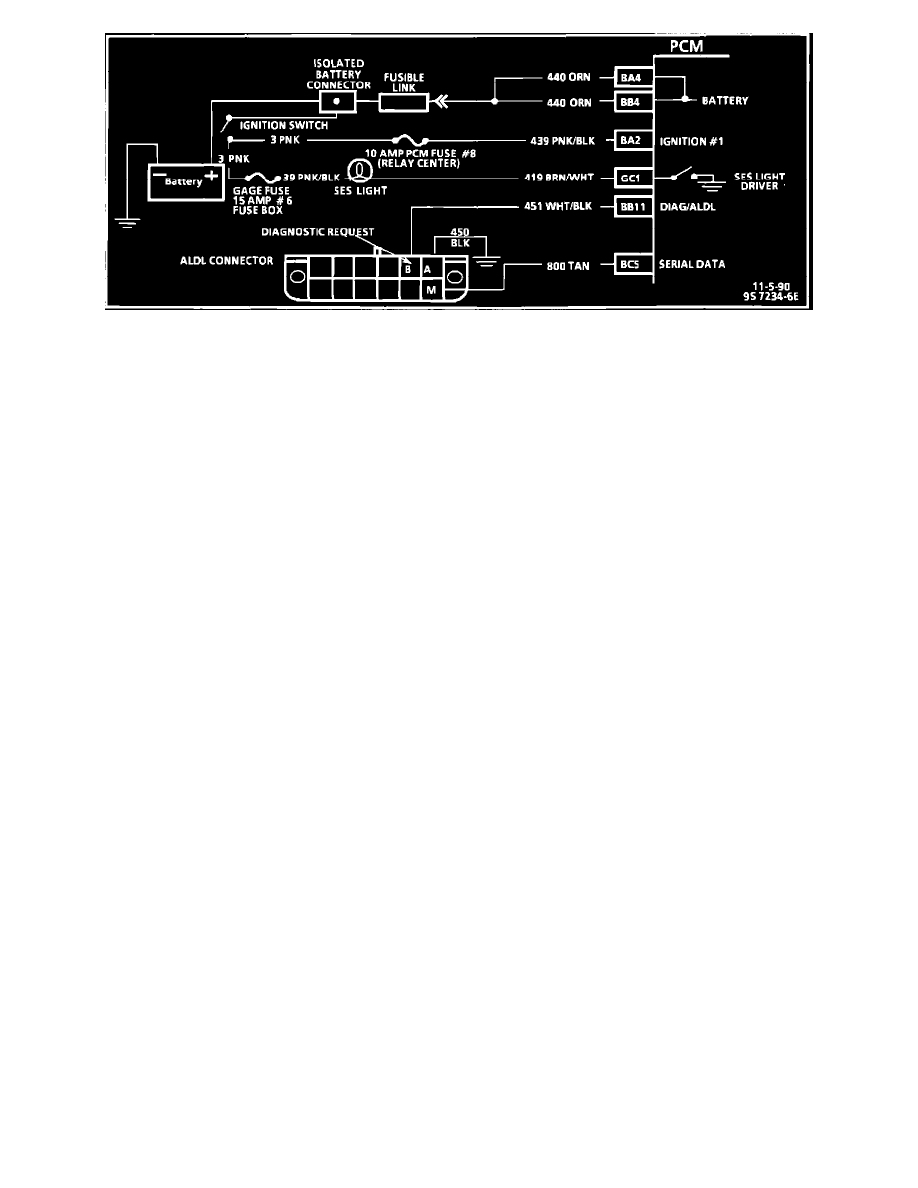
Diagnostic Circuit Diagram
NOTE:
a.
Numbers below refer to circled numbers in flow chart.
b.
Since this is the starting point for all diagnostic procedures or finding the cause of an emissions test failure, always begin here and always follow
the flow chart as directed.
c.
For trouble code diagnosis and Charts A-1 and A-2, refer to Computers and Control Systems. See: Powertrain Management/Computers and
Control Systems/Testing and Inspection
1.
Get an accurate description of the complaint and verify. Include filling out the DRIVEABILITY WORKSHEET and VEHICLE REPAIR
HISTORY. Refer to INFO TYPE/TECHNICAL MANAGEMENT SUPPORT for forms.
Perform Underhood Inspection:
a.
Check vacuum hoses for splits, kinks, and proper routing.
b.
Check ignition wires for cracking, hardness, and proper connections.
c.
Check all wiring for proper connections, pinches, and cuts.
d.
Check wiring harness for proper routing.
e.
Check for missing components.
2.
Check for manual updates, testing procedures, warranty and recall information.
3.
Refer to PROM I.D.
4.
Bulb Check - to check SES light circuit and that the computer can complete the circuit. The system check starts with a bulb check. If there is no
"SERVICE ENGINE SOON" light, See: Powertrain Management/Computers and Control Systems/Testing and Inspection/Diagnostic Trouble
Code Tests and Associated Procedures/Related Tests and Information/A Charts.
5.
Diagnostic Mode - this indicates if the diagnostic mode is working.
6.
"Scan" Data - this determines if the computer is supplying input and output visual data.
7.
Engine Start - this step is done after it has been determined that the computer will display codes and data.
8.
Other Codes - Proceed to the applicable chart if a code is displayed. Scanning the data for typical values may indicate a problem area if the values
are different from typical. Refer to Typical Scan Data Values. If all systems appear to be functioning, refer to Diagnostic Charts. See:
Powertrain Management/Computers and Control Systems/Testing and Inspection